ELM402 View Datasheet(PDF) - Elm Electronics
Part Name
Description
Manufacturer
ELM402 Datasheet PDF : 9 Pages
| |||
ELM402
Debouncing Circuits
Any time that two metal surfaces meet, as they do
inside a rotary encoder, there will be a tendency for
the moving one to bounce, which causes the electrical
connection to make and break. The duration of this
bouncing action may be very short, but it is usually fast
enough to cause multiple counts to be recorded by
connected electronic circuits. As the number of
bounces can not be predicted, a means of removing
them is necessary. Circuits that remove the bounce
are usually called ‘debouncing’ circuits.
Many debouncing circuits employ a simple timer to
determine if an input is stable. This generally works
well if the two contacts meet and then remain still. With
a rotary encoder however, one of the contacts meets
the other then usually continues sliding over the
surface of the stationary contact. This will produce
noise while the contact is sliding, occasionally enough
to make it look like there are more inputs.
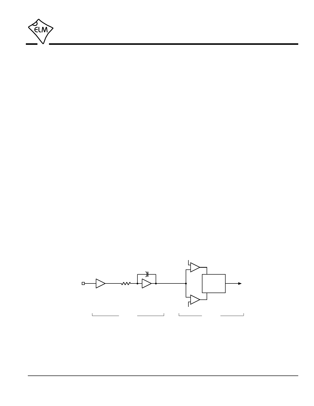
The ELM402 employs a two stage system to
remove the bounce and the sliding noise from the
input signal. A block diagram of the stages are shown
in figure 3. The first stage is a digital filter circuit that is
used to determine the average value of the waveform
over a time. If a long enough time is chosen, short
duration pulses will have little effect on the overall
average. If the time chosen is too long, however, the
circuit will be slow to respond, and may in fact average
out some legitimate inputs. Choosing the time period
(or time constant of the circuit) is thus very important in
determining how effective the filtering function will be.
We have found that with typical rotary encoder
specifications (usually 3.0 msec of bounce or noise,
maximum), the ELM402 debounce circuit works quite
well.
After the signal has been filtered, it is compared to
some reference levels, and the output of these
comparators are used to control a simple timer. The
timer is used to ensure that the output of the filter is
stable, and not just a momentary transient, while the
use of two comparator levels provides hysteresis, so
that some variation in the filter output can be tolerated.
Once the signals from the rotary encoder have
been debounced, they may be used by the direction
logic circuitry. The following section shows what the
ELM402 is able to produce from these signals.
rotary
encoder
input
tc = 1.7 msec
3 msec
timer
filter
timer
Figure 3. Internal Debouncing Logic
to
output
logic
ELM402DSA
Elm Electronics – Circuits for the Hobbyist
www.elmelectronics.com
6 of 9
Share Link: 