APU428 View Datasheet(PDF) - APLUS INTEGRATED CIRCUITS
Part Name
Description
Manufacturer
APU428 Datasheet PDF : 18 Pages
| |||
APU428
enable the counter from the first FIN rising edge to the next rising edge, then will generate an interrupt. It may
also use FREQ (internal frequency generator output) as clock input, hence counting the CX interval. For
measuring the resistor value of the temperature and humidity sensor, we must first measure the frequency of
Rref, then the frequency of Sensor:
Fref= K / Rref CX and
Fsensor= K / Rsensor CX, hence
Rsensor = Rref * Freq / Fsensor.
The CX input can be used as a clock counter.
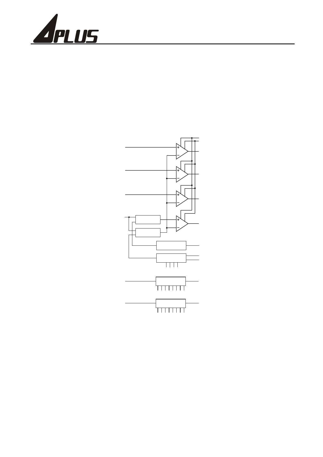
Analog-to-Digital converter
The diagram is shown below:
AN1
LHCP
ENCP
ADF1
AN2
ADF2
AN3
ADF3
AN4
MPW1
MPW2
2 o 1
Analog Switch
2 o 1
Analog Switch
LBR
Low Battery
Reference
DAC
4-Bit Ladder
DAC
0123
6 / 8-Bit
PWM DAC
0123 4567
6 / 8-Bit
PWM DAC
0123 4567
ADF4
ENLBR
ENDAC
MDA
MPW1
MPW2
The use of these blocks is illustrated below:
y Comparator: Sets negative input as AN4, compare with AN1, 2, 3.
y 4-bit ADC: Sets negative input as internal 4-bit DAC, positive input as AN4, software control for AN1, 2, 3,
4 analog value archive.
y Low battery detector: Sets negative input as internal 4-bit DAC, positive input as LBR (low battery
reference). If the DAC level is lower than LBR, it means there is a low-battery condition.
y PWM DAC output: With an external RC network, 6-bit or 8-bit PWM DAC can be used.
y 6-bit/ 8-bit ADC: Sets negative input as AN4, connects from PWM with an external RC network. You can
get analog value from AN1, 2, 3.
y Supply voltage measurement: Sets negative input as AN4, connects from PWM with an external RC
network, positive input is LBR. If comparative data is N, the supply voltage is LBR (about 1.26V) * 255 / N.
Note: The internal 4-bit DAC level is 1/32 VDD for 0, 3/32 for 1, 29/32 for E and 31/32 for F. The level of 6-bit
PWM is 0/63, 1/63, 62/63 and 63/63, and the level of 8-bit PWM is 0/255, 1/255, 254/255 and 255/255.
Preliminary
10
Ver. 0.0
Share Link: 