APU428 View Datasheet(PDF) - APLUS INTEGRATED CIRCUITS
Part Name
Description
Manufacturer
APU428 Datasheet PDF : 18 Pages
| |||
APU428
Functional Description
Index SRAM
The 256 X 4 bits index SRAM is used for applications that need more SRAM or need to load addresses by
operation, and data SRAM is included at a lower-half address in the index SRAM.
Index ROM
The 256 X 8 bits index ROM can be used in the 4-bit or 8-bit mode.
I/O ports
The IOA port can be selected by software separately as input or output. It can also be selected with/without
internal pull-low and different chattering clocks for a HALT release / interrupt trigger in order to reduce the
input bounce for the key scan:
PH6: 512Hz, PH8: 128Hz, PH10: 32Hz.
The pull-low of IOA will be masked off for those pins defined as output pins:
The IOA port can be used as a pseudo serial output port.
The IOB port can be selected by software separately as input or output.
Th e IOC port can be selected by software separately as input or output, and with/without internal pull-low and
different chattering clocks for a HALT release /interrupt trigger in order to reduce the bounce of the key scan.
The pull-low of the IOC will be masked off for those pins defined as output pins.
The IOD port can be selected by software separately as input or output.
The IOD port can be used as a pseudo serial output port.
The initial state of all I/O ports is the standard input state, and IOA and C have pull-low.
Before setting the I/O ports from input to output, execute the output function first to ensure the output state.
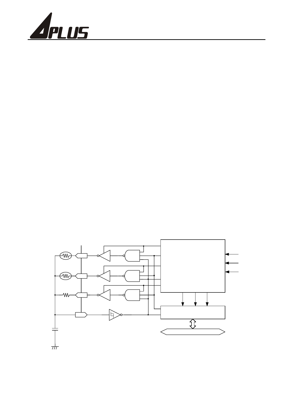
Resistor to frequency converter
We use an RC oscillation circuit and a 16-bit counter to calculate the relative resistance of temperature and
humidity sensor. The diagram is shown below:
RTP
RT
RHM
RH
Rref
RR
ELP
ENX
EHM
FIN
ERR
TMS
Timer & R/F
PH9
Controller
MRF
Freq. CL LD
ENX
Freq. CL LD
CX
FIN
16-Bit Counter
CX
4-Bit Data Bus
There are 2 methods for measuring the input frequency. First, set FIN (i.e. CX) as the clock input and use
timer 2 or the software directly as interval control. Second, if the FIN (CX) frequency is too low (either because
of a poor resolution for a fixed interval or a longer interval for better resolution but a longer read-out rate,
ex.10 seconds per read-out), you can switch the measure mode to set FIN (CX) as the interval control. It will
Preliminary
9
Ver. 0.0
Share Link: 