GS7032 View Datasheet(PDF) - Giga Semiconductor
Part Name
Description
Manufacturer
GS7032 Datasheet PDF : 11 Pages
| |||
GS70328SJ/TS
Power Supply Currents
0 to 70°C
-40 to 85°C
Parameter Symbol Test Conditions
7 ns 8 ns 10 ns 12 ns 15 ns 7 ns 8 ns 10 ns 12 ns 15 ns
Operating
Supply IDD
Current
CE ≤ VIL
All other inputs
≥ VIH or ≤ VIL
Min. cycle time
IOUT = 0 mA
75 mA 65 mA 50 mA 50 mA 50 mA 80 mA 70 mA 55 mA 55 mA 55 mA
Standby
Current
ISB1
CE ≥ VIH
All other inputs
≥ VIH or ≤VIL
Min. cycle time
35 mA 30 mA 25 mA 25 mA 25 mA 40 mA 35 mA 30 mA 30 mA 30 mA
CE ≥ VDD – 0.2 V
Standby
Current
ISB2
All other inputs
≥ VDD – 0.2 V or
1 mA
2 mA
≤ 0.2 V
AC Test Conditions
Parameter
Conditions
Input high level
Input low level
Input rise time
Input fall time
Input reference level
Output reference level
Output load
VIH = 2.4 V
VIL = 0.4 V
tr = 1 V/ns
tf = 1 V/ns
1.4 V
1.4 V
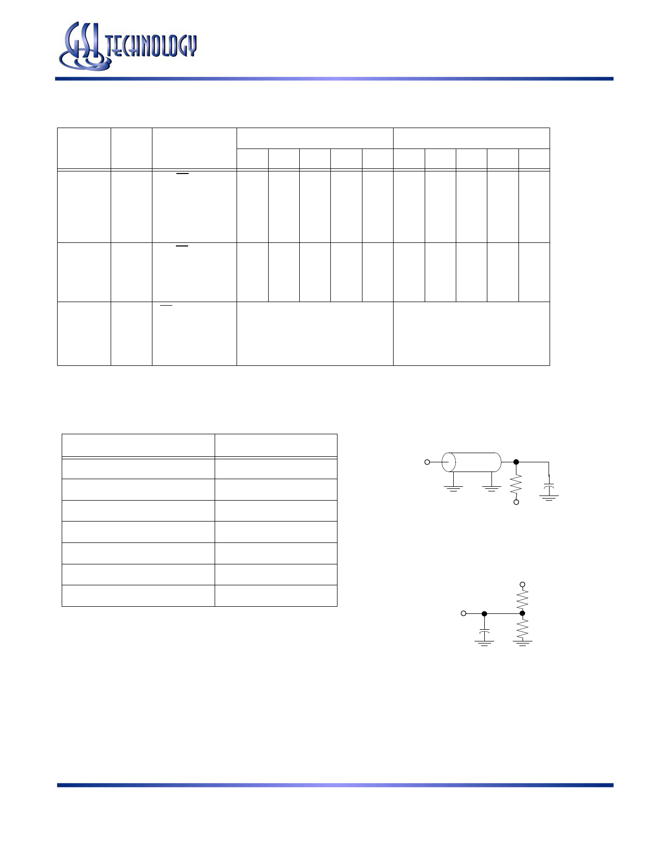
Fig. 1& 2
Notes:
1. Include scope and jig capacitance
2. Test conditions as specified with output loading as shown in Fig. 1
unless otherwise noted
3. Output load 2 for tLZ, tHZ, tOLZ and tOHZ
Output Load 1
DQ
50Ω 30pF1
VT = 1.4 V
Output Load 2
3.3 V
DQ
589Ω
5pF1 434Ω
Rev: 1.11 11/2004
4/11
Specifications cited are subject to change without notice. For latest documentation see http://www.gsitechnology.com.
© 1999, GSI Technology
Share Link: 