H11AV1 View Datasheet(PDF) - Fairchild Semiconductor
Part Name
Description
Manufacturer
H11AV1 Datasheet PDF : 7 Pages
| |||
GlobalOptoisolator™
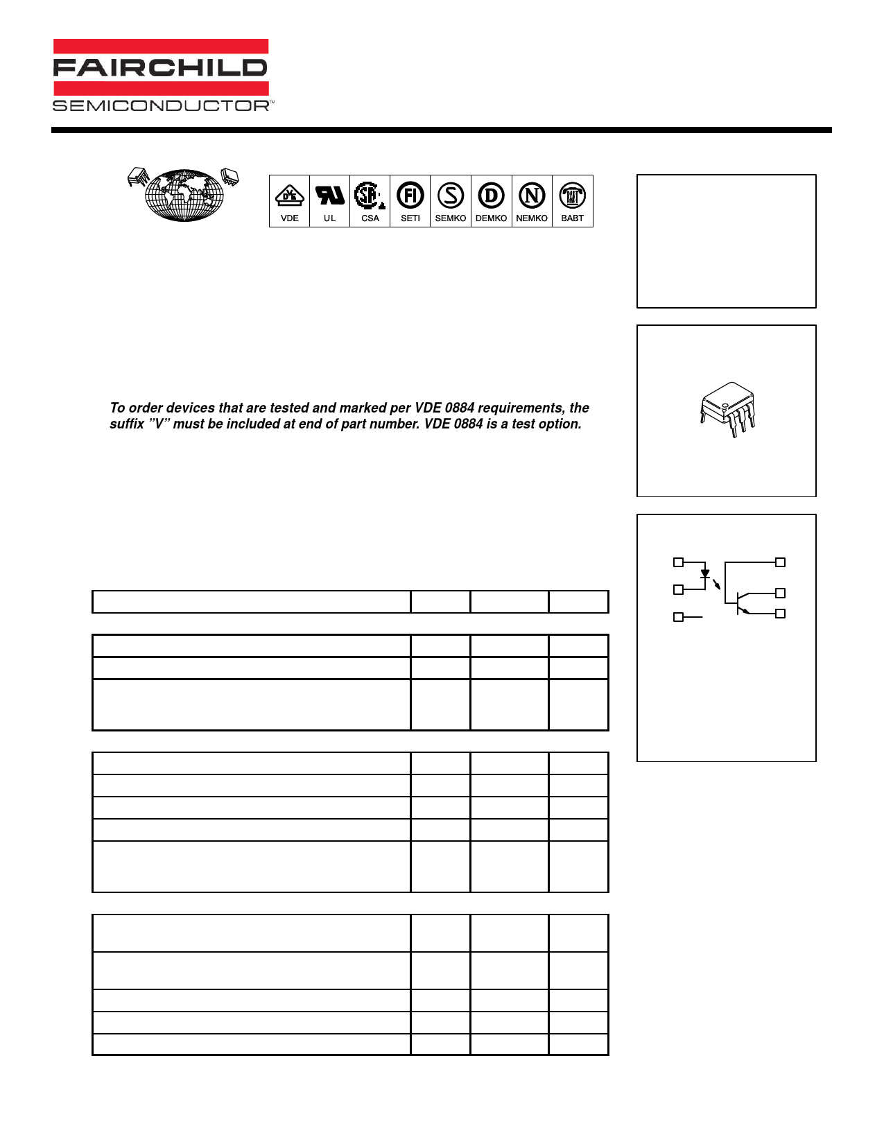
6-Pin DIP Optoisolators
Transistor Output
The H11AV1,A and H11AV2,A devices consist of a gallium arsenide infrared
emitting diode optically coupled to a monolithic silicon phototransistor detector.
• Guaranteed 70 Volt V(BR)CEO Minimum
• ‘A’ Suffix = 0.400″ Wide Spaced Leadform (Same as ‘T’ Suffix.)
• To order devices that are tested and marked per VDE 0884 requirements, the
suffix ”V” must be included at end of part number. VDE 0884 is a test option.
Applications
• General Purpose Switching Circuits
• Interfacing and coupling systems of different potentials and impedances
• Monitor and Detection Circuits
• Regulation and Feedback Circuits
• Solid State Relays
MAXIMUM RATINGS (TA = 25°C unless otherwise noted)
Rating
Symbol
Value
INPUT LED
Reverse Voltage
Forward Current — Continuous
LED Power Dissipation @ TA = 25°C
with Negligible Power in Output Detector
Derate above 25°C
VR
6
IF
60
PD
120
1.41
OUTPUT TRANSISTOR
Collector–Emitter Voltage
Emitter–Base Voltage
Collector–Base Voltage
Collector Current — Continuous
Detector Power Dissipation @ TA = 25°C
with Negligible Power in Input LED
Derate above 25°C
VCEO
70
VEBO
7
VCBO
70
IC
150
PD
150
1.76
TOTAL DEVICE
Isolation Surge Voltage(1)
(Peak ac Voltage, 60 Hz, 1 sec Duration)
VISO
7500
Total Device Power Dissipation @ TA = 25°C
Derate above 25°C
PD
250
2.94
Ambient Operating Temperature Range
TA
– 55 to +100
Storage Temperature Range
Tstg – 55 to +150
Soldering Temperature (10 sec, 1/16″ from case)
TL
260
1. Isolation surge voltage is an internal device dielectric breakdown rating.
1. For this test, Pins 1 and 2 are common, and Pins 4, 5 and 6 are common.
Unit
Volts
mA
mW
mW/°C
Volts
Volts
Volts
mA
mW
mW/°C
Vac(pk)
mW
mW/°C
°C
°C
°C
H11AV1,A
H11AV2,A
61
STANDARD THRU HOLE
SCHEMATIC
1
6
2
5
3
4
PIN 1. LED ANODE
2. LED CATHODE
3. N.C.
4. EMITTER
5. COLLECTOR
6. BASE
Share Link: 