HA16114FP View Datasheet(PDF) - Hitachi -> Renesas Electronics
Part Name
Description
Manufacturer
HA16114FP Datasheet PDF : 38 Pages
| |||
HA16114P/PJ/FP/FPJ, HA16120FP/FPJ
1.2 External Synchronization
These ICs have a sync input pin so that they can be synchronized to a primary-control AC/DC converter.
Pulses from the secondary winding of the switching transformer should be dropped through a resistor
voltage divider to the sync input pin. Synchronization takes place at the falling edge, which is optimal for
multiple-output power supplies that synchronize with a flyback AC/DC converter.
The sync input pin (SYNC) is connected internally through a synchronizing circuit to the sawtooth
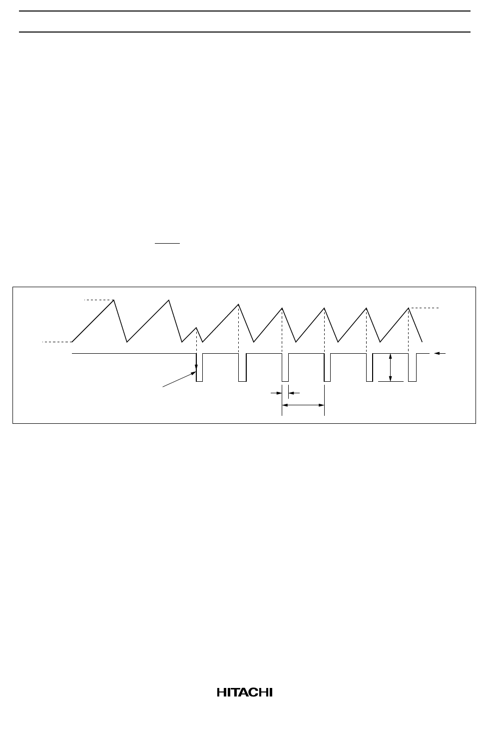
oscillator to synchronize the sawtooth waveform (see figure 1.2).
• Synchronization is with the falling edge of the external sync signal.
• The frequency of the external sync signal must be in the range fOSC < fSYNC < fOSC × 2.
• The duty cycle of the external sync signal must be in the range 5% < t1/t2 < 50% (t1 = 300 ns Min).
• With external synchronization, VTH' can be calculated as follows.
VTH’ = (VTH − VTL) ×
fOSC
fSYNC
+ VTL
Note: When not using external synchronization, connect the SYNC pin to the Vref pin.
VTH (1.6 V typ)
Sawtooth wave
(fOSC)
VTL
(1.0 V typ)
SYNC pin
(f SYNC )
Synchronized
t1
at falling edge
t2
Figure 1.2 External Synchronization
VTH
Vref
1V
8
Share Link: 