HN58X2402SFPIE View Datasheet(PDF) - Renesas Electronics
Part Name
Description
Manufacturer
HN58X2402SFPIE
Renesas Electronics

HN58X2402SFPIE Datasheet PDF : 19 Pages
| |||
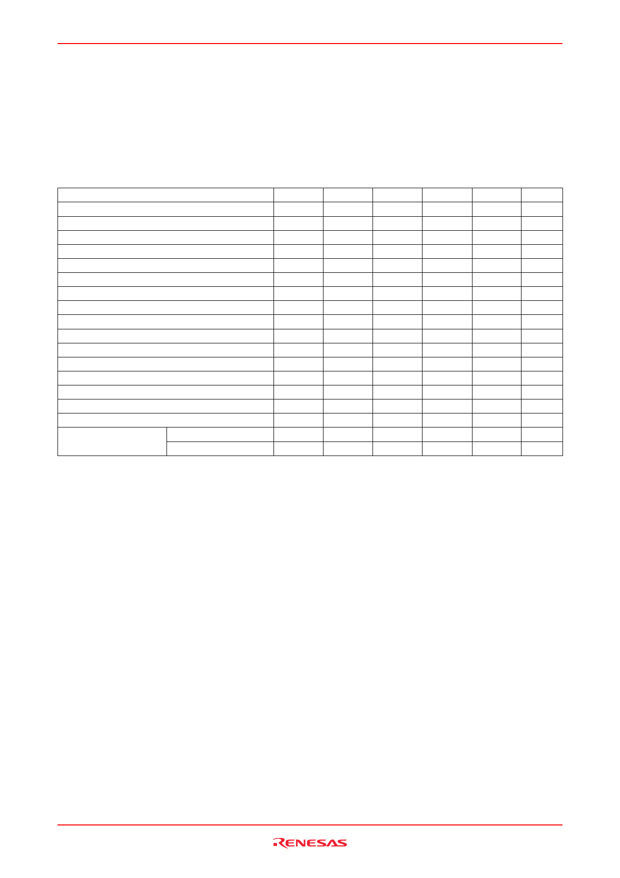
HN58X2402SI/HN58X2404SI
AC Characteristics (Ta = −40 to +85°C, VCC = 1.8 to 5.5 V)
Test Conditions
• Input pules levels:
 VIL = 0.2 × VCC
 VIH = 0.8 × VCC
• Input rise and fall time: ≤ 20 ns
• Input and output timing reference levels: 0.5 × VCC
• Output load: TTL Gate + 100 pF
Parameter
Symbol
Min
Typ
Max
Clock frequency
fSCL


400
Clock pulse width low
tLOW
1200


Clock pulse width high
tHIGH
600


Noise suppression time
tI


50
Access time
tAA
100

900
Bus free time for next mode
tBUF
1200


Start hold time
tHD.STA
600


Start setup time
tSU.STA
600


Data in hold time
tHD.DAT
0


Data in setup time
tSU.DAT
100


Input rise time
tR


300
Input fall time
tF


300
Stop setup time
tSU.STO
600


Data out hold time
tDH
50


Write protect hold time
tHD.WP
1200


Write protect setup time
tSU.WP
0


Write cycle time
VCC = 2.7 V to 5.5 V
tWC


10
VCC = 1.8 V to 2.7 V
tWC


15
Notes: 1. This parameter is sampled and not 100% tested.
2. tWC is the time from a stop condition to the end of internally controlled write cycle.
Unit Notes
kHz
ns
ns
ns
1
ns
ns
ns
ns
ns
ns
ns
1
ns
1
ns
ns
ns
ns
ms
2
ms
2
Rev.4.00, Jul.13.2005, page 4 of 17
Share Link: