HT1382 View Datasheet(PDF) - Holtek Semiconductor
Part Name
Description
Manufacturer
HT1382 Datasheet PDF : 29 Pages
| |||
HT1382
I2C/3-Wire Real Time Clock
Clock Compensation
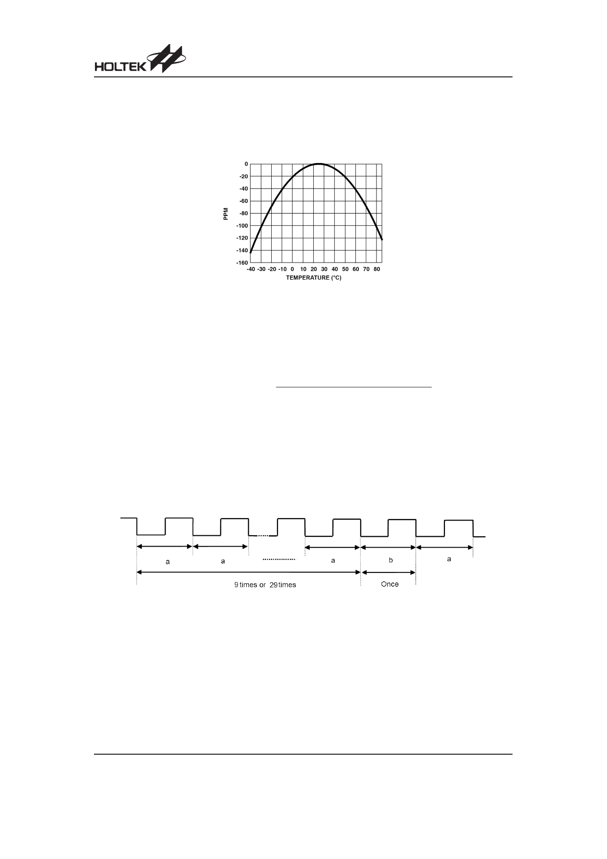
The device includes a digital trimming method for clock error correction due to temperature variations
of the crystal oscillator. This can be implemented as manufacturing calibration or user active
calibration. The crystal accuracy to temperature characteristic is similar to that shown in the diagram.
The Digital Trimming Register, DT, is used for clock compensation. Correction is performed once
every 10 seconds or 30 seconds. The minimum resolution is 3.052ppm or 1.017ppm and the device has
a correction in the range of ±192.276ppm or ±64.071ppm.
Set FO3~FO0= ²1010², the FOUT pin will have 1Hz clock pulse output. Measure the FOUT
frequency using a high-accuracy frequency counter with 7 or more digits. The correction value is
calculated using the formula shown below.
Correction value = integral value (
1Hz - (measured value)
)
minimum resolution (3.052ppm or 1.014ppm)
When clock compensation is used, set FO3~FO0=²1010², and the FOUT pin will have 1Hz clock
pulse output. The cycle changes once in 10 seconds or in 30 seconds as shown below. In the diagram
²a² denotes a non-correctional cycle, and ²b² denotes a correctional cycle. Measure ²a² and ²b² using a
high-accuracy frequency counter of 7 or more digits. Calculate the average frequency based on the
measured result.
For DTS = 0, the average period = (a ´ 9 + b) ¸ 10
For DTS = 1, the average period = (a ´ 29 + b) ¸ 30
Rev. 1.40
10
May 27, 2011
Share Link: 