ICS93722 View Datasheet(PDF) - Integrated Circuit Systems
Part Name
Description
Manufacturer
ICS93722 Datasheet PDF : 6 Pages
| |||
ICS9372 2
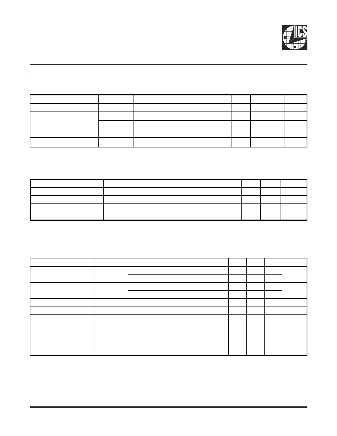
Recommended Operating Conditions
TA = 0 - 70°C; Supply Voltage AVDD, VDD = 2.5 V +/-0.2V (unless otherwise stated)
PARAMETER
SYMBOL
CONDITIONS
MIN
TYP
MAX
UNITS
Analog / Core Supply Voltage VDD, AVDD
2.3
2.5
2.7
V
Input Voltage Level
VIL
VIH
VDD/2 + 0.5V
VDD/2 - 0.5V
V
V
Inpu Duty Cycle
IDC
40
60
Input max jitter
ITCYC
500
ps
Timing Requirements
TA = 0 - 70°C; Supply Voltage AVDD, VDD = 2.5 V +/-0.2V (unless otherwise stated)
PARAMETER
SYMBOL
CONDITIONS
MIN
Operating Clock Frequency1
freqop
66
Input Clock Duty Cycle1
dtin
40
Clock Stabilization1
tSTAB
from VDD = 2.5V to 1% target
frequency
1. Guaranteed by design, not 100% tested in production.
TYP MAX
200
60
100
UNITS
MHz
%
µs
Switching Characteristics
TA = 0 - 70°C; Supply Voltage VDD = 2.5 V +/-0.2V (unless otherwise stated)
PARAMETER
SYMBOL
CONDITIONS
MIN TYP MAX
Absolute Jitter1
Tjabs
66 MHz
120
100 - 200 MHz
75
Cycle to cycle Jitter1,2
Phase Error1
Output to output Skew1
Pulse Skew1
Duty Cycle (differential)1,3
Tcyc-cyc
t(phase error)
Tskew
Tskewp
DC
Rise Time, Fall Time1
tR, tF
66 MHz
100 - 200 MHz
CLK_INT to FB_INT
VT = 50%
VT = 50%, 66 MHz to 100 MHz
VT = 50%, 101 MHz to 167 MHz
Single-ended 20 - 80 %
Load = 120Ω / 12 pF
50 110
25 65
-150 50 150
70 100
100
49.5 50 50.5
49 50 51
450 550 950
1. Guaranteed by design, not 100% tested in production.
2. Refers to transistion on non-inverting output.
3. While the pulse skew is almost constant over frequency, the duty cycle error increases at higher frequencies.
This is due to the formula: duty cycle = twH / tC, where the cycle time (tC) decreases as the frequency increases.
UNITS
ps
ps
ps
ps
ps
%
ps
0539E—07/18/03
4
Share Link: 