ICX285AQ View Datasheet(PDF) - Sony Semiconductor
Part Name
Description
Manufacturer
ICX285AQ
Sony Semiconductor

ICX285AQ Datasheet PDF : 24 Pages
| |||
ICX285AQ
Image Sensor Characteristics Measurement Method
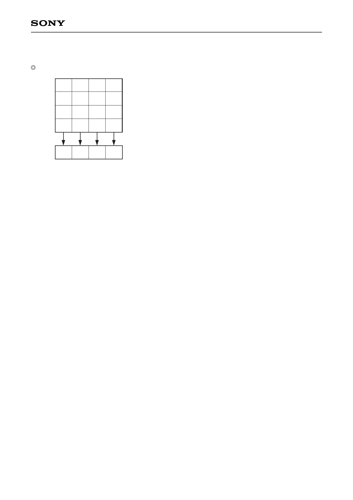
Color coding of this image sensor & Readout
Gb B Gb B
R Gr R Gr
Gb B Gb B
R Gr R Gr
The primary color filters of this image sensor are arranged in the
layout shown in the figure on the left (Bayer arrangement).
Gr and Gb denote the G signals on the same line as the R signal
and the B signal, respectively.
Horizontal register
Color Coding Diagram
All pixels' signals are output successively in a 1/15s period.
The R signal and Gr signal lines and the Gb signal and B signal lines are output successively.
– 11 –
Share Link: