IRU1075 View Datasheet(PDF) - International Rectifier
Part Name
Description
Manufacturer
IRU1075 Datasheet PDF : 6 Pages
| |||
IRU1075
Assuming the following specifications:
VIN = 5V
VOUT = 3.5V
IOUT(MAX) = 4.6A
TA = 35!C
The steps for selecting a proper heat sink to keep the
junction temperature below 135°C is given as:
1) Calculate the maximum power dissipation using:
PD = IOUT × (VIN - VOUT)
PD = 4.6 × (5 - 3.5) = 6.9W
2) Select a package from the regulator data sheet and
record its junction to case (or tab) thermal resistance.
Selecting TO-220 package gives us:
θJC = 2.7!C/W
3) Assuming that the heat sink is black anodized, cal-
culate the maximum heat sink temperature allowed:
Assume, θcs = 0.05°C/W (heat-sink-to-case ther-
mal resistance for black anodized)
4) With the maximum heat sink temperature calculated
in the previous step, the heat-sink-to-air thermal re-
sistance (θSA) is calculated by first calculating the
temperature rise above the ambient as follows:
∆T = TS - TA = 116 - 35 = 81!C
∆T = Temperature Rise Above Ambient
θSA
=
∆T
PD
=
81
6.9
=
11.7!C/W
5) Next, a heat sink with lower θsa than the one calcu-
lated in Step 4 must be selected. One way to do this
is to simply look at the graphs of the “Heat Sink Temp
Rise Above the Ambient” vs. the “Power Dissipation”
and select a heat sink that results in lower tempera-
ture rise than the one calculated in previous step.
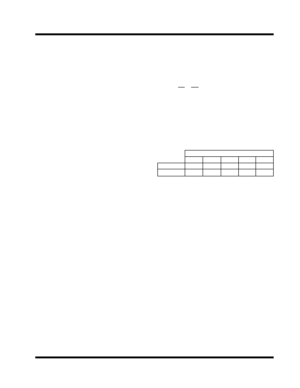
The following heat sinks from AAVID and Thermalloy
meet this criteria.
Thermalloy
AAVID
Air Flow (LFM)
0
100
200
300
400
6021PB 6021PB 6073PB 6109PB 7141D
534202B 534202B 507302 575002 576802B
TS = TJ - PD × (θJC + θCS)
TS = 135 - 6.9 × (2.7 + 0.05) = 116!C
Rev. 1.1
06/29/01
5
Share Link: 