IRU1175 View Datasheet(PDF) - International Rectifier
Part Name
Description
Manufacturer
IRU1175 Datasheet PDF : 6 Pages
| |||
IRU1175
The IRU1175 keeps a constant 1.25V between the
Vsense pin and the Vadj pin. By placing a resistor R1
across these two pins and connecting the Vsense and
Vout pin together, a constant current flows through R1,
adding to the Iadj current and into the R2 resistor pro-
ducing a voltage equal to the (1.25/R1)*R2 + Iadj*R2.
This voltage is then added to the 1.25V to set the output
voltage. This is summarized in the above equation. Since
the minimum load current requirement of the IRU1175 is
10mA, R1 is typically selected to be a 121Ω resistor so
that it automatically satisfies this condition. Notice that
since the Iadj is typically in the range of 50µA it only
adds a small error to the output voltage and should be
considered when very precise output voltage setting is
required.
Load Regulation
For most applications a minimum of 100µF aluminum
electrolytic capacitor such as Sanyo, MVGX series,
Panasonic FA series as well as the Nichicon PL series
insures both stability and good transient response.
Thermal Design
The IRU1175 incorporates an internal thermal shutdown
that protects the device when the junction temperature
exceeds the allowable maximum junction temperature.
Although this device can operate with junction tempera-
tures in the range of 150°C, it is recommended that the
selected heat sink be chosen such that during maxi-
mum continuos load operation the junction temperature
is kept below this number. The example below shows
the steps in selecting the proper surface mount pack-
age.
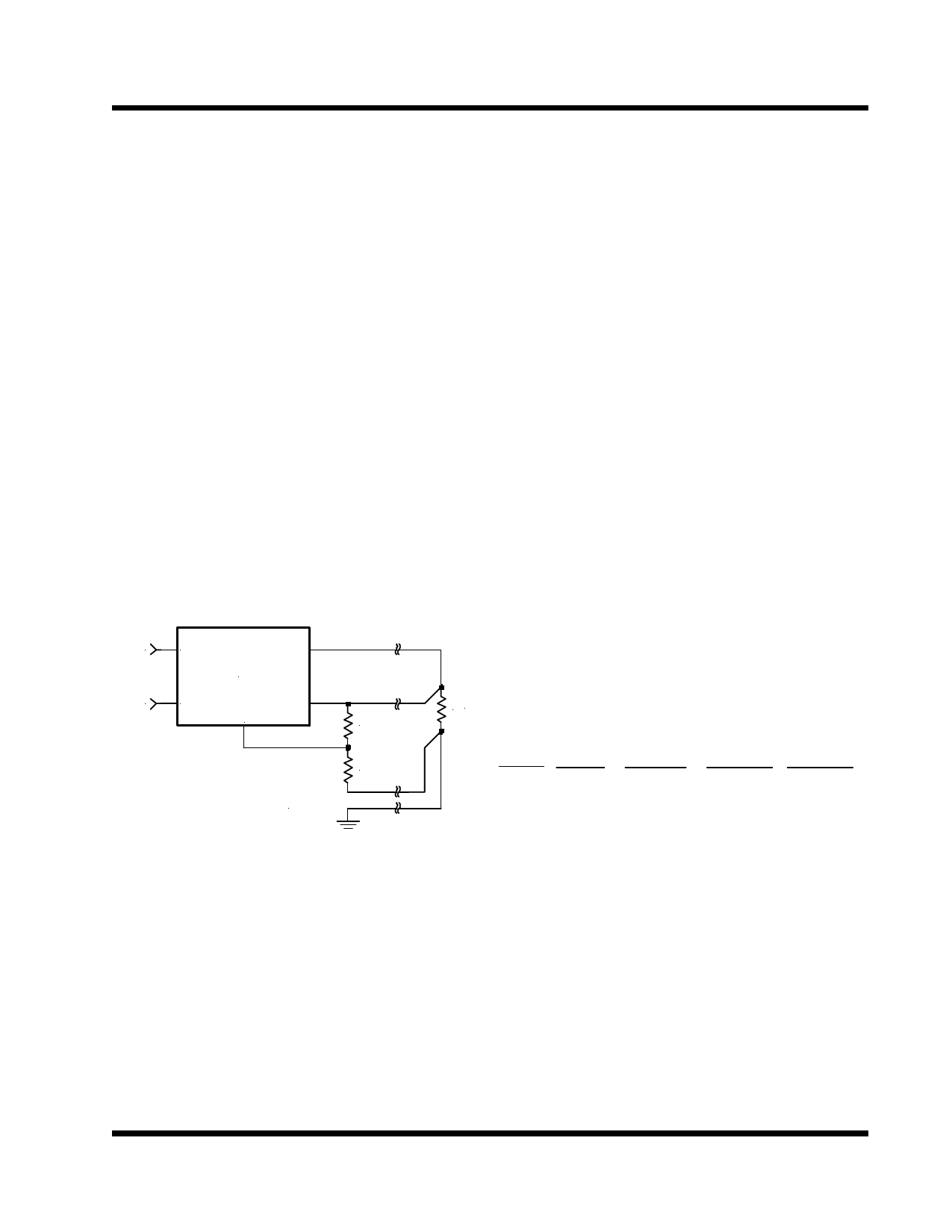
Since the IRU1175 has separate pins for the output (Vout)
and the sense (Vsense), it is ideal for providing true re-
mote sensing of the output voltage at the load. This
means that the voltage drops due to parasitic resistance
such as PCB traces between the regulator and the load
are compensated for using remote sensing. Figure 3
shows a typical application of the IRU1175 with remote
sensing.
Assuming, the following conditions:
Vout=2.7V
Vin=3.3V
Vctrl=5V
Iout=2A DC Avg
Calculate the maximum power dissipation using the fol-
lowing equation:
Vin
Vin
Vout
IRU1175
Vctrl
Vctrl
Vsense
Adj
R1
Pd=Iout*(Vin-Vout) + (Iout/60)*(Vctrl - Vout)
Pd=2*(3.3-2.7) + (2/60)*(5-2.7)=1.28 W
RL Using table below select the proper package and the
amount of copper board needed.
R2
1175app3-1.0
Figure 3 - Schematic showing connection for best
load regulation
Stability
The IRU1175 requires the use of an output capacitor as
part of the frequency compensation in order to make the
regulator stable. Typical designs for the microproces-
sor applications use standard electrolytic capacitors with
typical ESR in the range of 50 to 100mΩ and an output
capacitance of 500 to 1000µF. Fortunately as the ca-
pacitance increases, the ESR decreases resulting in a
fixed RC time constant. The IRU1175 takes advantage
of this phenomena in making the overall regulator loop
stable.
Pkg Copper θJA(°C/W)
Area
TO-263 1.4"X1.4" 25
TO-263 1.0"X1.0" 30
TO-263 0.7"X0.7" 35
TO-263 Pad Size 45
SO-8 1.0"X1.0" 55
Max Pd
(Ta=25°C)
4.4W
3.7W
3.1W
2.4W
2.0W
Max Pd
(Ta=45°C)
3.6W
3.0W
2.6W
2.0W
1.63W
Note: Above table is based on the maximum junction
temperature of 135°C.
As shown in the above table, any of the two packages
will do the job. For low cost applications the SO-8 pack-
age is recommended.
Rev. 1.2
11/29/99
2-83
Share Link: 