L5170 View Datasheet(PDF) - STMicroelectronics
Part Name
Description
Manufacturer
L5170 Datasheet PDF : 9 Pages
| |||
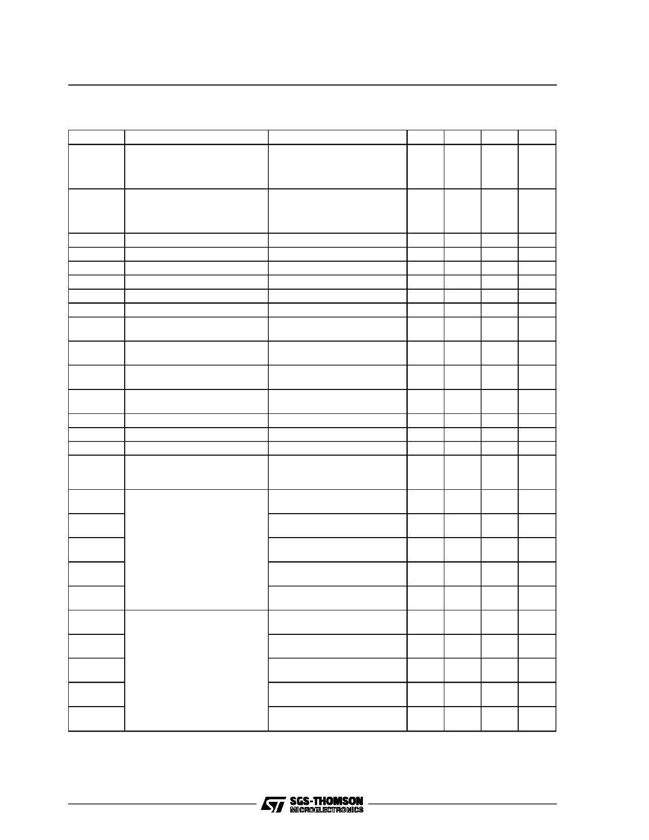
L5170
AC ELECTRICAL CHARACTERISTICS (VCC = 9 to 11V; VEE = – 9 to – 11V Tamb =0 to 70°C, unless
otherwise specified
Symbol
Parameter
Test Condition
Min. Typ. Max. Unit
VOH
High Level Output Voltage
Vin = 0.8V
RL = inf
5
RL = 3KΩ
5
RL = 450Ω (see note 1)
4.5
6
V
6
V
6
V
VOL
Low Level Output Voltage
Vin = 2.4V
RL = inf
–6
RL = 3KΩ
–6
RL = 450Ω (see note 1)
–6
–5
V
–5
V
– 4.5
V
VOl
Output Voltage Balance
|VCC| = |VEE|; RL = 450Ω
0.4
V
VIH
High Level Input Voltage
2
V
VIL
Low Level Input Voltage
0.8
V
VIK
Input Clamp Voltage
IIN = – 15mA
– 1.5
V
IIH
High Level Input Current
VIN = 2.4V
40
µA
IIL
Low Level Input Current
VIN = 0.4V
– 400
µA
ICC
Positive Supply Current
VIN = 2.4V; RS = 2KΩ; RL = 3KΩ
CL = 2.5nF; (See note 2)
30
mA
ICC1
Positive Supply Current
VIN = 0.4V; RS = 2KΩ; RL = 3KΩ
CL = 2.5nF; (See note 2)
40
mA
IEE
Negative Supply Current
VIN = 2.4V; RS = 2KΩ; RL = 3KΩ – 30
mA
CL = 2.5nF; (See note 2)
IEE1
Negative Supply Current
VIN = 0.4V; RS = 2KΩ; RL = 3KΩ – 40
mA
CL = 2.5nF; (See note 2)
Ish
Output Short Circuit Current
VO = 0V; VIN = 2.4V; (see fig.1) 25
100 mA
Isl
Output Short Circuit Current
VO = 0V; VIN = 2.4V; (see fig.1) – 100
– 25 mA
Ibal
Output Current Balance
Ish/Isl = Ibal
0.625
1.6 mA/mA
Ix
Output Leakage Current
See fig.2,3 and note 3
VO = 6V
VO = – 6V
– 70
70
µA
µA
tr
Rise time (see note 4 and 5; see RL = 450Ω; CL = 50pF
2
figure 4A)
Rslew = 5.34KΩ ±1%
2.7
µs
trc1
RL = 450Ω; CL = 0.01µF
10
µs
Rslew = 10KΩ ±1%
trc2
RL = 450Ω; CL = 0.1µF
50
µs
Rslew = 10KΩ ±1%
trc3
RL = 450Ω; CL = 2.5nF
0.65
1.2
µs
Rslew = 2KΩ ±1%
trc4
RL = 450Ω; CL = 2.5nF
3.25
6
µs
Rslew = 10KΩ ±1%
tf
Fall time (see note 4 and 5; see RL = 450Ω; CL = 50pF
2
figure 4A)
Rslew = 5.34KΩ ±1%
2.7
µs
tfc1
RL = 450Ω; CL = 0.01µF
10
µs
Rslew = 10KΩ ±1%
tfc2
RL = 450Ω; CL = 0.1µF
50
µs
Rslew = 10KΩ ±1%
tfc3
RL = 450Ω; CL = 2.5nF
0.65
1.2
µs
Rslew = 2KΩ ±1%
tfc4
RL = 450Ω; CL = 2.5nF
3.25
6
µs
Rslew = 10KΩ ±1%
Note 1: The Output under load must not drop below 90% of the open circuit drive level.
Note 2: This represents the static condition only. Applications can see 130mA normal current draw for clock and data lines with up to 500mA
transients when all lines are transitioning at the same time. Over 500ft of cable slew rate is governed by the drivers ability to sink current.
The currents are rougly equivalent to the short circuit current.
3/9
Share Link: 