L9907 View Datasheet(PDF) - STMicroelectronics
Part Name
Description
Manufacturer
L9907 Datasheet PDF : 8 Pages
| |||
L9907N
ELECTRICAL CHARACTERISTICS (7V < VS < 18V, –40°C < Tj < 150°C; unless otherwise specified.)
Symbol
Iq
Parameter
Quiescent Current
-VN-, VN+ Neutral Zone Threshold (2)
-VST- ,VST+ Stop Range Threshold
VINCL
VINCH
VCH (3)
Control Input LOW Disable
Threshold
Control Input HIGH Disable
Threshold (4)
IIN
Input Bias Current
VOSI
VOSO
Output Saturation Voltage
Sink Stage
Output Saturation Voltage
Source Stage
Test Condition
IOUT = 0, (Output Open)
|Vdin| < 20mV (stop)
|Vdin| < 200mV (L or R)
1.5 < VINC < VS -2V; VS = 12V
RPR = ∞
RPR = 0
1.5 < VINC < VS -2V; VS = 12V
RPR = ∞
RPR = 0
Tj = -40 to +25ºC
Tj = >25ºC
Outputs = ON
with RINC = 0Ω
with RINC = 5KΩ
with RINC = 10KΩ
Outputs = OFF
with RINC = 0Ω
with RINC = 5KΩ
with RINC = 10KΩ
1.5 < VINC < VS -2V; VS = 12V
Vdin = 0; RPR = ∞
Vdin = ± 200mV; RPR = ∞
Vdin = 0; RPR = 0
Vdin = ± 200mV; RPR = 0
IOUT = 0.7A
IOUT = 0.35A
IOUT = 0.7A
IOUT = 0.35A
Min. Typ. Max. Unit
7
9
mA
6
7
mA
3 x VST 120
4x
mV
3 x VST 240 VST mV
4 x VST
25
38
60
mV
50
76
100 mV
0.8
1.2
1.5
V
0.6
1.2
1.5
V
VS-2
V
VS-1.5 V
VS-1.4 V
VS-0.8
V
VS-0.6
V
VS-0.4
V
0.45 2.0
µA
0.9
4.0
µA
0.8
3.6
µA
1.5
6.8
µA
1.1
1.4
V
0.8
1.1
V
1.2
2
V
0.9 1.5
V
(2) With a programming resistor RPR between the PR pin and GND the N+ and N- thresholds can be adjusted from the nominal value (RPR = ∞
, pin PR open) up to two times the nominal value (RPR = 0, pin PR shorted to GND).
1 + RPR
The
formula
defining
VN+,
VN-
typical
value
as
a
function
of
RPR
and
VS
is:
–VN−
=
VN+
=
(36mV
+
0.017⋅
VS)
⋅
1
+
2
9.5KΩ
⋅ RPR
.
9.5KΩ
for RPR = ∞ this formula reduced to:
-VN+ (RPR = ∞) = VN+ (RPR = ∞) = 18mV + 0.0086 ⋅ VS.
for Vs in V and RPR in KΩ these formulas result in mV
(3) VCH is the control input voltage applied to the pin INC through a serial resistor RINC
(4) OUTPUTS = UNDEFINED for: VS -2V < VCH (RINC = 0Ω) < VS -0.8V
VS -1.5V < VCH (RINC = 5KΩ) < VS -0.6V
VS -1.4V < VCH (RINC = 10KΩ) < VS -0.4V
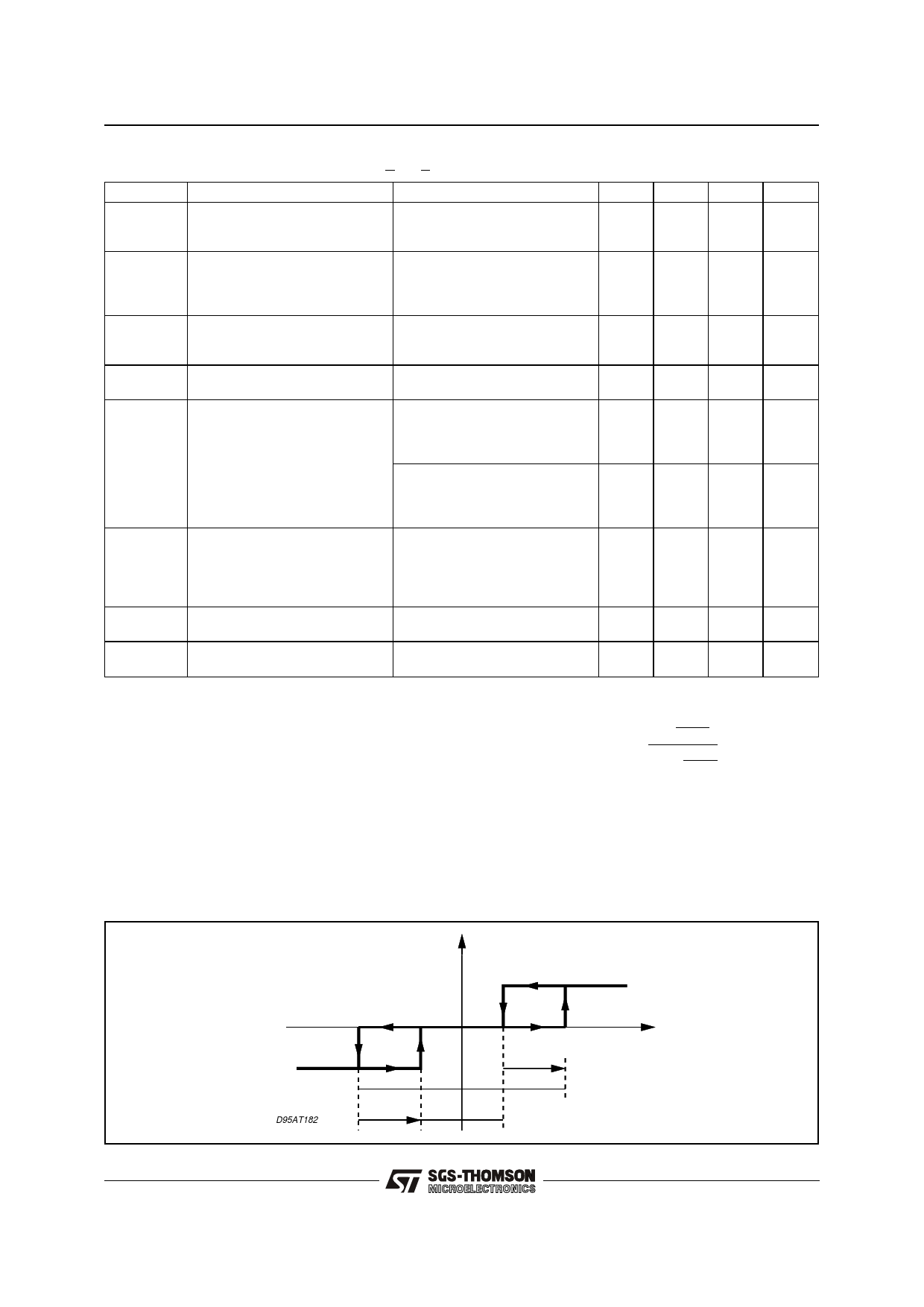
Figure 1: L9907N Differential Input to Output Transfer Characteristics
VM =VOUTC -VOUTF
VN-
MOTOR
DIRECTION RIGHT
VH-
D95AT182
MOTOR
DIRECTION LEFT
VN+
VH+
VINC -VINF
NEUTRALZONE
STOP RANGE
3/8
Share Link: 