L9909 View Datasheet(PDF) - STMicroelectronics
Part Name
Description
Manufacturer
L9909 Datasheet PDF : 9 Pages
| |||
L9909
ELECTRICAL CHARACTERISTICS (continued.)
Pin Symbol
Parameter
Test Condition
INPUT OUTPUT TRANSER FUNCTION
VCOM
VFB
COSC
M+
M-
AV
VSTP
VSTR
Vof f_c1
Input Output Gain
Stop Motor Voltage
Start Error Voltage
Comp 1 Input Offset Voltage
Ton
Switch on Delay
Toff
Switch off Delay
VCOM
Rdiff
Differential Input Impedance
VFB
(see fig 3)
VSTP = 2 VR4
VSTR = VR7/5
Error Voltage when the motor
starts braking
2VCOM − VFB
Icom − IFB
Rcom
Common Mode Input (see fig 3) VCOM + VFB
Icom + IFB
Min. Typ. Max. Unit
7 10 14
2.5 3 3.5 V
1 1.5 2 %VCC
-20
20 mV
1
1
100 300
2 TOSC
2 TOSC
KΩ
50
KΩ
OUTPUT DRIVERS
M+
RON_H
High Side RDS
M-
RON_L
Low Side RDS
ILIM
TR
TF
VMTRAN
THSHDN
Output Current Limit for each
of 4 Output Transistors
Separately
Output Rise Time
Output Fall Time
|V(M+) - V(M-)| Output Voltage
During VCC Transients
Thermal Shutdown
IM+ = IM- = 0.3A; VCC =13.5V
IM+ = IM- = 0.3A; VCC =7V
IM+ = IM- = 0.3A; VCC =13.5V
IM+ = IM- = 0.3A; VCC =7V
20% to 80%
80% to20%
Transients of figs.4 and 5
0.6 1.5 Ω
1 2.6 Ω
0.6 1.5 Ω
1 2.6 Ω
1
1.9 A
20
µs
20
µs
20 V
170
°C
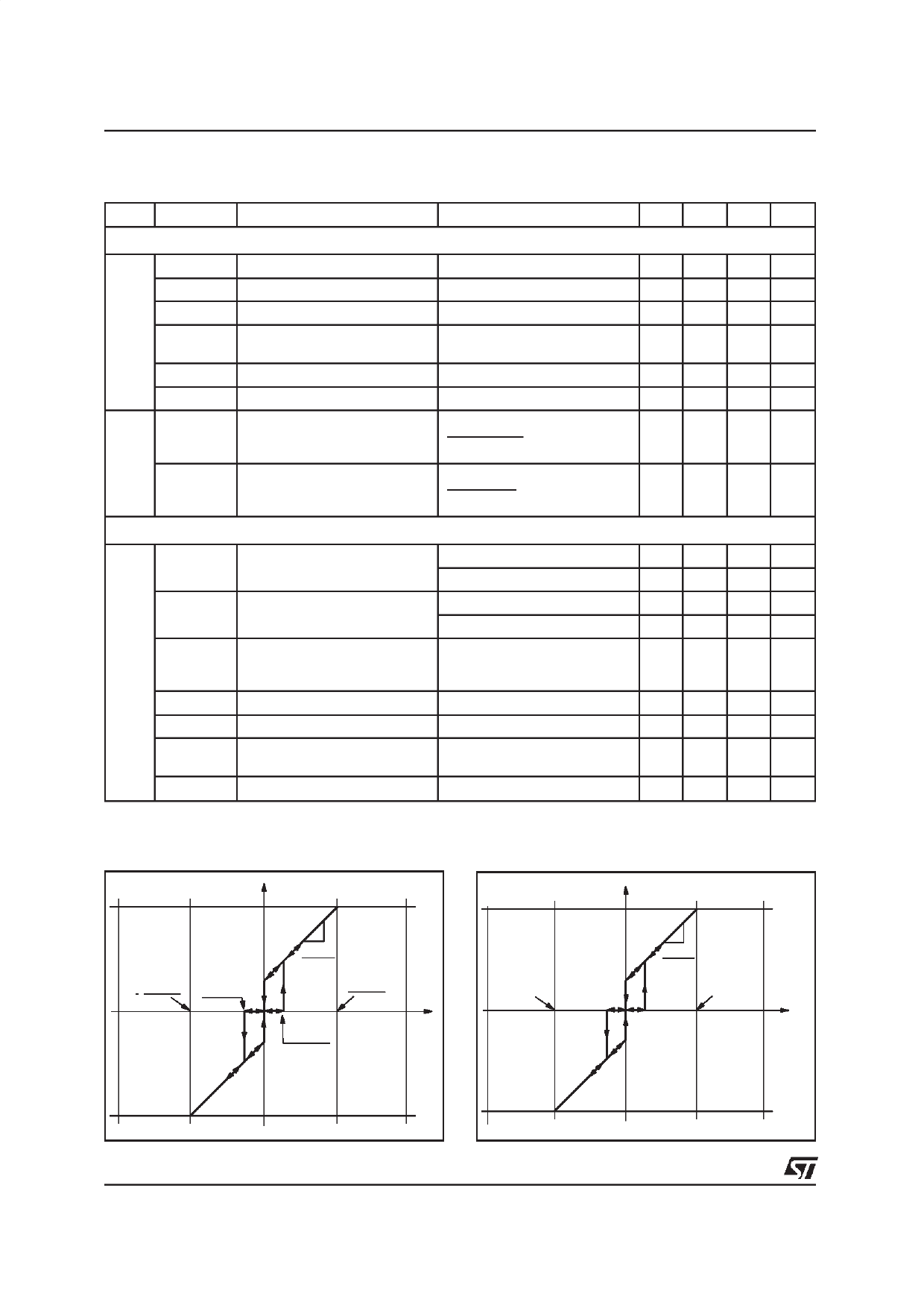
Figure 1. Static Transfer Characteristic. Error
Voltage vs. Output Voltage
VOUT
Vcc
Figure 2. Static Transfer Characteristic. Position
Error Voltage vs. Output Voltage
Perr = Verr/VCC
VOUT
Vcc
Vcc-VSTP
10
-Vcc
VSTR = VSTP
-1.5% Vcc
∆VOUT =10
∆Verr
Vcc-VSTP
10
Verr
VSTR =
Vcc
1.5% Vcc
-VSTP
-10 (1+V-S--T-P---)
Vcc
-100
VS TP
-1.5
1.5
∆VOUT =10
∆Verr
10 (1+V--S-T--P--)
Vcc
100
Perr [%]
-VSTP
-Vcc
-Vcc
4/9
Share Link: 