LA75501V View Datasheet(PDF) - SANYO -> Panasonic
Part Name
Description
Manufacturer
LA75501V
SANYO -> Panasonic

LA75501V Datasheet PDF : 10 Pages
| |||
LA75501V
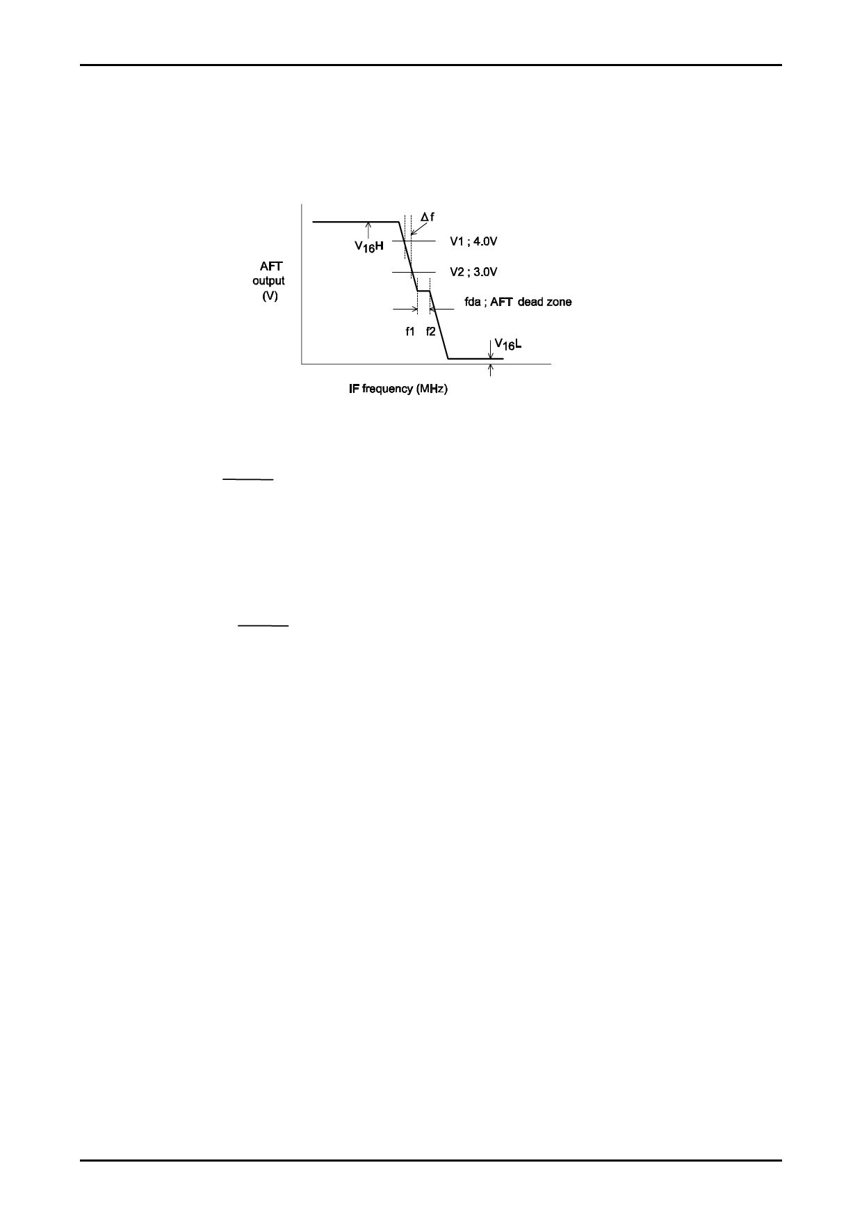
V18. V19. Maximum, minimum AFT voltage, AFT detection sensitivity [V16H, V16L]
(1) Internal AGC
(2) fp = 38.9MHz ±1.5MHz Vi = 10mVrms (VIF input)
(3) Measure maximum and minimum AFT output voltage (at the measuring point B) by changing the input
frequency.
(4) Maximum voltage: V16H, minimum voltage: V16L.
V20.V21.V22.V23. AFT tolerance 1,2,AFT detector sensitivity, AFT Dead Zone [dfa, Sf, fda]
(1) Measure the frequency deviation when the voltage at the measuring point B changes from V1 to V2. ·····∆f
V1−V2
Sf (mV/kHz) = ∆f
(2) Measure the width in which the voltage at the measuring point B does not change.
(3) Calculate as follows:
fda (kHz) = f2 − f1
(4) Calculate as follows:
IF Center frequency: 38.9MHz, 38MHz
dfa (kHz) = fc−
f1 + f2
2
V24.V25. APC pull-in range [fpu, fpl]
(1) Internal AGC
(2) FLL: Free
(3) fp = 33MHz to 44MHz CW;10mVrms
(4) Adjust the SG signal frequency to be higher than fp = 38.9MHz to bring the PLL to unlocked state.
Note; The PLL is taken as in unlocked state when a beat signal appears at test point A.
(5) When the SG signal frequency is lowered, the PLL is brought to locked state again. ····· f1
(6) Lower the SG signal frequency to bring the PLL to unlock state.
(7) When the SG signal frequency is raised, the PLL is brought to locked state again. ····· f2
(8) Calculate as follows:
fpu = f1 − 38.9MHz
fpl = f2 − 38.9MHz
V26.V27. VCO maximum variable range (U, L) [dfu, dfl]
(1) Apply the VCC voltage to the external AGC, IF AGC (pin 18).
(2) fl is taken as the frequency when 1V is applied to the APC pin (pin 9). In the same manner,
fu is taken as the frequency when 5V is applied to the APC pin (pin 9).
dpu = fu − 38.9MHz
dfl = fl − 38.9MHz
No.A0224-8/10
Share Link: