LA7577N View Datasheet(PDF) - SANYO -> Panasonic
Part Name
Description
Manufacturer
LA7577N Datasheet PDF : 16 Pages
| |||
LA7577N
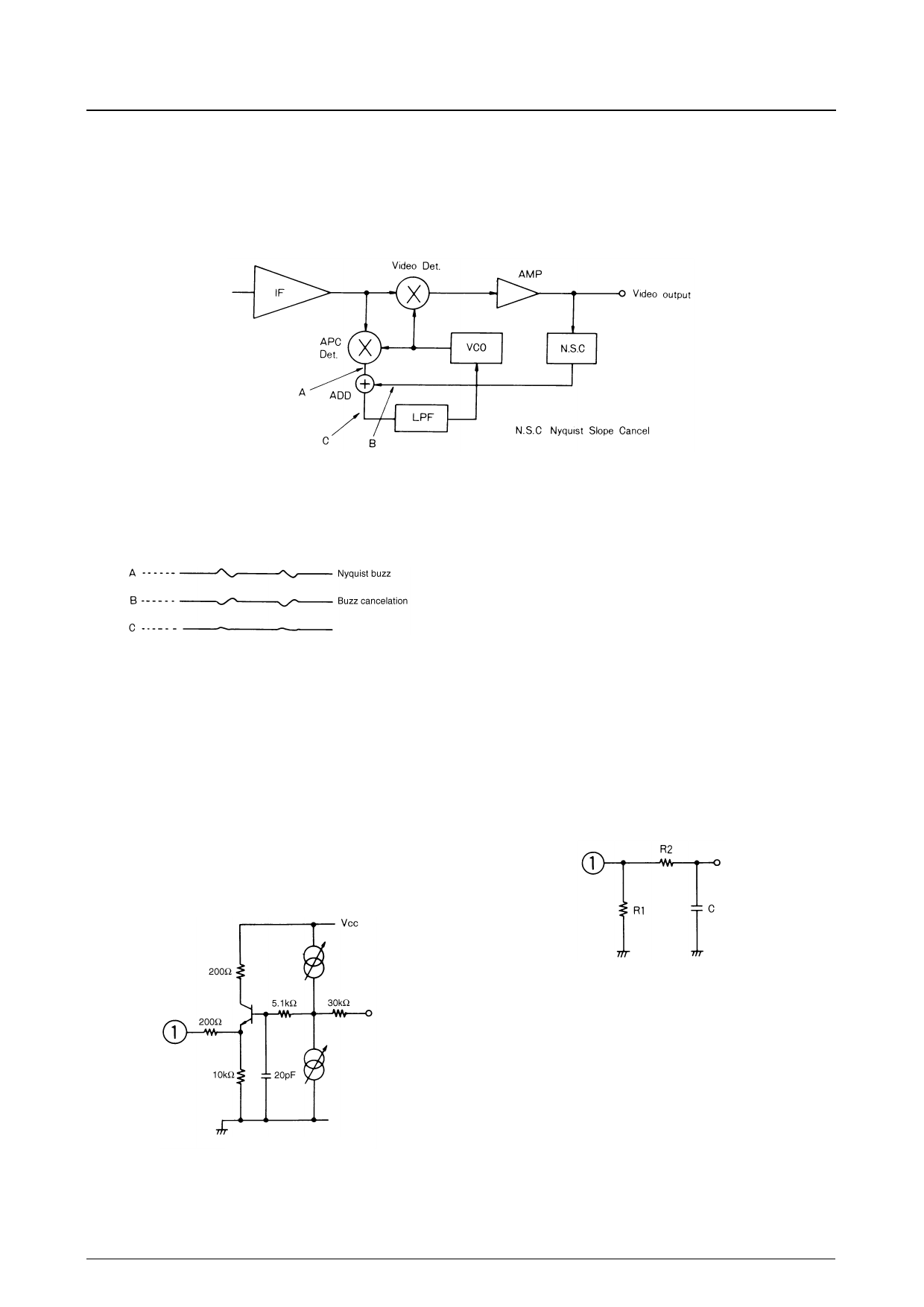
This phase distortion is the cause of audio buzz, or
Nyquist buzz, because the VCO synchronizes to the com-
posite vector. A Nyquist buzz cancelation circuit is incor-
porated into the LA7577N to reduce the level of this noise
as shown in Figure 3.
Figure 3. PLL detector with buzz cancelation
A typical signal with Nyquist buzz is shown in Figure 4
together with the compensating signal generated by the
Nyquist-slope canceler and the resultant signal.
The circuit shown in Figure 3 is highly effective in sup-
pressing audio buzz caused by the 4.5MHz IF beat signal
in Japanese multiplexed (L − R) audio or American (MTS)
Multichannel TV Sound (L − R) signals.
Figure 4. Nyquist buzz cancelation waveforms
As buzz cancelation is independent of the PLL loop time
constant, other parameters such as automatic phase control
can be optimized to eliminate interference from flyback
pulses.
Design Notes
FM Detector Output (Pin 1)
The FM detector output is an emitter follower with a
200Ω series protection resistor as shown in Figure 5.
In multiplex audio applications where pin 1 is connected
to the input of a multiplexed audio decoder, the input
resistance of the decoder can decrease, causing distortion
of the (L − R) signal. In this case, a 5.1kΩ or larger resis-
tor, R1, should be connected between pin 1 and ground.
In monophonic applications, an RC de-emphasis circuit
should be connected as shown in Figure 6. The time con-
stant is given by R2 × C.
Figure 6. RC de-emphasis circuit
Figure 5. FM detector output
No. 4037—8/16
Share Link: 