LB11824 View Datasheet(PDF) - SANYO -> Panasonic
Part Name
Description
Manufacturer
LB11824
SANYO -> Panasonic

LB11824 Datasheet PDF : 17 Pages
| |||
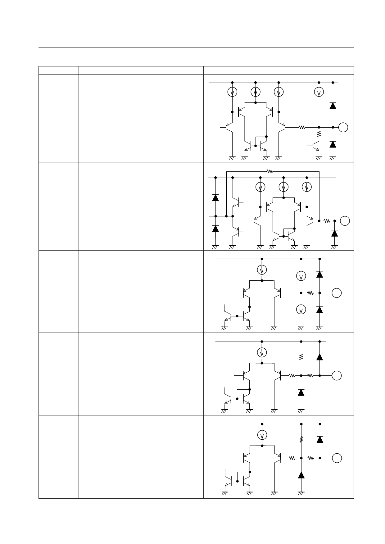
Continued from preceding page.
Pin No. Symbol
Pin Description
LB11824M
VCC2
Equivalent circuit
Pin to set the PWM oscillation frequency.
21
PWM
Connect a capacitor between this pin and GND.
200Ω
21
2kΩ
VCC2
34kΩ
22
VCTL
Control voltage input pin. For control with this pin, set the
PWMIN pin to the L level.
2.26V
40kΩ
22
Pin to set the operation time of motor lock protection circuit
and to set the initial reset pulse.
23
CSD Connect a capacitor between this pin and GND. When the
protection circuit is not to be used, connect a capacitor and
resistor (150kW, 4700pF) in parallel between this pin and
GND.
VREG
VREG
24
S/S
Start/stop control pin. Start with L and stop with H or in the
open condition
300Ω
23
50kΩ
3.5kΩ
24
VREG
PWM pulse input pin. Output drive with L and output OFF
25
PWM with H or in the open condition. For control with this pin,
IN apply the voltage of VCTL2 voltage or more to the VCTL
pin.
50kΩ
3.5kΩ
25
Continued on next page.
No. 7107-8/17
Share Link: