LPC1764 View Datasheet(PDF) - Philips Electronics
Part Name
Description
Manufacturer
LPC1764 Datasheet PDF : 66 Pages
| |||
NXP Semiconductors
LPC1769/68/67/66/65/64
32-bit ARM Cortex-M3 microcontroller
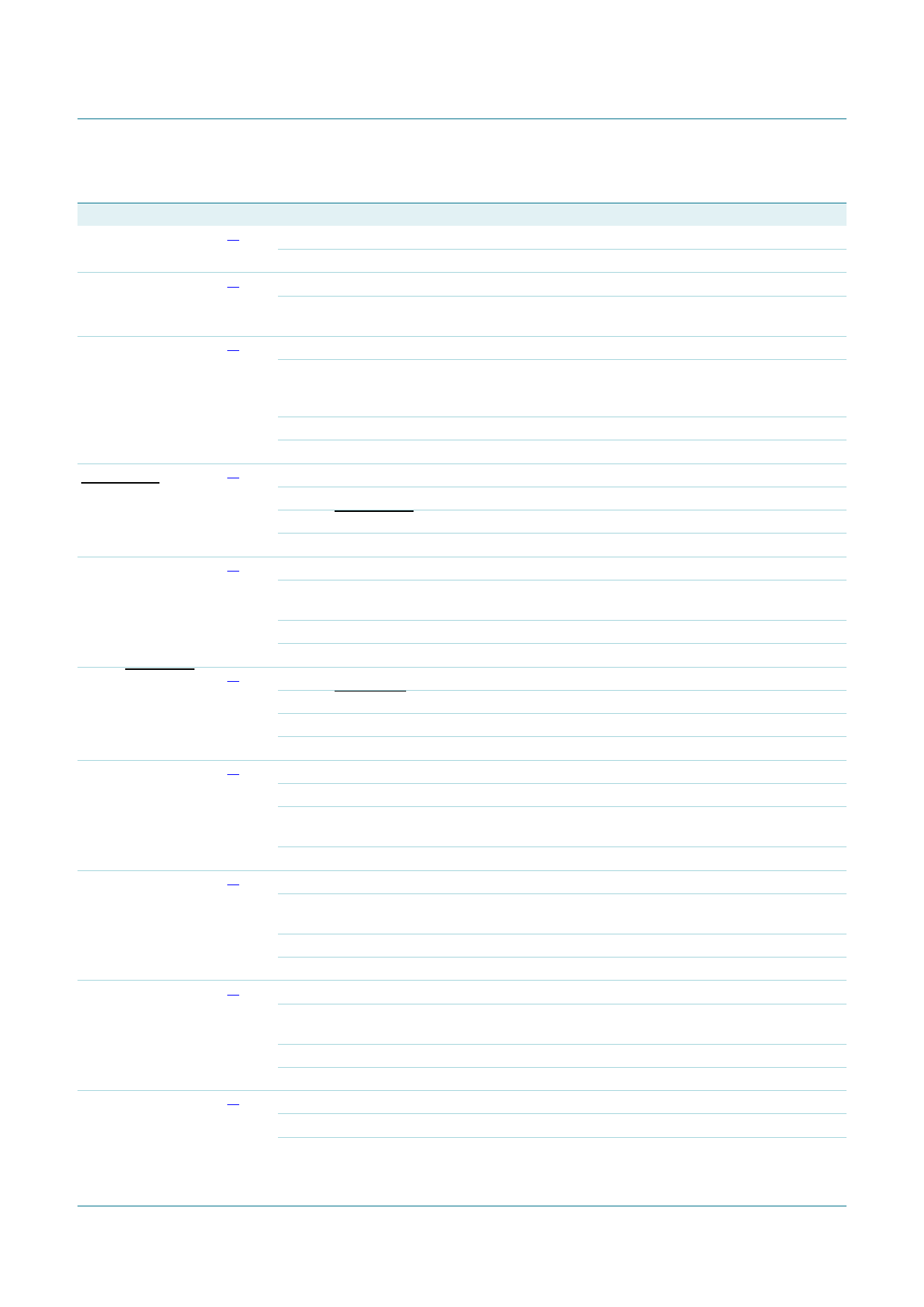
Table 3. Pin description …continued
Symbol
Pin
Type Description
P1[16]/
ENET_MDC
87[1]
I/O P1[16] — General purpose digital input/output pin.
O
ENET_MDC — Ethernet MIIM clock (LPC1769/68/67/66/64 only).
P1[17]/
ENET_MDIO
86[1]
I/O P1[17] — General purpose digital input/output pin.
I/O ENET_MDIO — Ethernet MIIM data input and output. (LPC1769/68/67/66/64
only).
P1[18]/
USB_UP_LED/
PWM1[1]/
CAP1[0]
32[1]
I/O P1[18] — General purpose digital input/output pin.
O
USB_UP_LED — USB GoodLink LED indicator. It is LOW when device is
configured (non-control endpoints enabled). It is HIGH when the device is not
configured or during global suspend. (LPC1769/68/66/65/64 only).
O
PWM1[1] — Pulse Width Modulator 1, channel 1 output.
I
CAP1[0] — Capture input for Timer 1, channel 0.
P1[19]/MCOA0/
USB_PPWR
CAP1[1]
33[1]
I/O P1[19] — General purpose digital input/output pin.
O
MCOA0 — Motor control PWM channel 0, output A.
O
USB_PPWR — Port Power enable signal for USB port. (LPC1769/68/66/65 only).
I
CAP1[1] — Capture input for Timer 1, channel 1.
P1[20]/MCI0/
PWM1[2]/SCK0
34[1]
I/O P1[20] — General purpose digital input/output pin.
I
MCI0 — Motor control PWM channel 0, input. Also Quadrature Encoder Interface
PHA input.
O
PWM1[2] — Pulse Width Modulator 1, channel 2 output.
I/O SCK0 — Serial clock for SSP0.
P1[21]/MCABORT/ 35[1]
PWM1[3]/
SSEL0
I/O P1[21] — General purpose digital input/output pin.
O
MCABORT — Motor control PWM, LOW-active fast abort.
O
PWM1[3] — Pulse Width Modulator 1, channel 3 output.
I/O SSEL0 — Slave Select for SSP0.
P1[22]/MCOB0/
USB_PWRD/
MAT1[0]
36[1]
I/O P1[22] — General purpose digital input/output pin.
O
MCOB0 — Motor control PWM channel 0, output B.
I
USB_PWRD — Power Status for USB port (host power switch, LPC1769/68/66/65
only).
O
MAT1[0] — Match output for Timer 1, channel 0.
P1[23]/MCI1/
PWM1[4]/MISO0
37[1]
I/O P1[23] — General purpose digital input/output pin.
I
MCI1 — Motor control PWM channel 1, input. Also Quadrature Encoder Interface
PHB input.
O
PWM1[4] — Pulse Width Modulator 1, channel 4 output.
I/O MISO0 — Master In Slave Out for SSP0.
P1[24]/MCI2/
PWM1[5]/MOSI0
38[1]
I/O P1[24] — General purpose digital input/output pin.
I
MCI2 — Motor control PWM channel 2, input. Also Quadrature Encoder Interface
INDEX input.
O
PWM1[5] — Pulse Width Modulator 1, channel 5 output.
I/O MOSI0 — Master Out Slave in for SSP0.
P1[25]/MCOA1/
MAT1[1]
39[1]
I/O P1[25] — General purpose digital input/output pin.
O
MCOA1 — Motor control PWM channel 1, output A.
O
MAT1[1] — Match output for Timer 1, channel 1.
LPC1769_68_67_66_65_64_4
Product data sheet
Rev. 04 — 1 February 2010
© NXP B.V. 2010. All rights reserved.
10 of 66
Share Link: 