LT1764EQ-1.8(RevA) View Datasheet(PDF) - Linear Technology
Part Name
Description
Manufacturer
LT1764EQ-1.8 Datasheet PDF : 16 Pages
| |||
LT1764 Series
APPLICATIO S I FOR ATIO
The LT1764 series are 3A low dropout regulators opti-
mized for fast transient response. The devices are capable
of supplying 3A at a dropout voltage of 340mV. The low
operating quiescent current (1mA) drops to less than 1µA
in shutdown. In addition to the low quiescent current, the
LT1764 regulators incorporate several protection features
which make them ideal for use in battery-powered sys-
tems. The devices are protected against both reverse input
and reverse output voltages. In battery backup applica-
tions where the output can be held up by a backup battery
when the input is pulled to ground, the LT1764-X acts like
it has a diode in series with its output and prevents reverse
current flow. Additionally, in dual supply applications
where the regulator load is returned to a negative supply,
the output can be pulled below ground by as much as 20V
and still allow the device to start and operate.
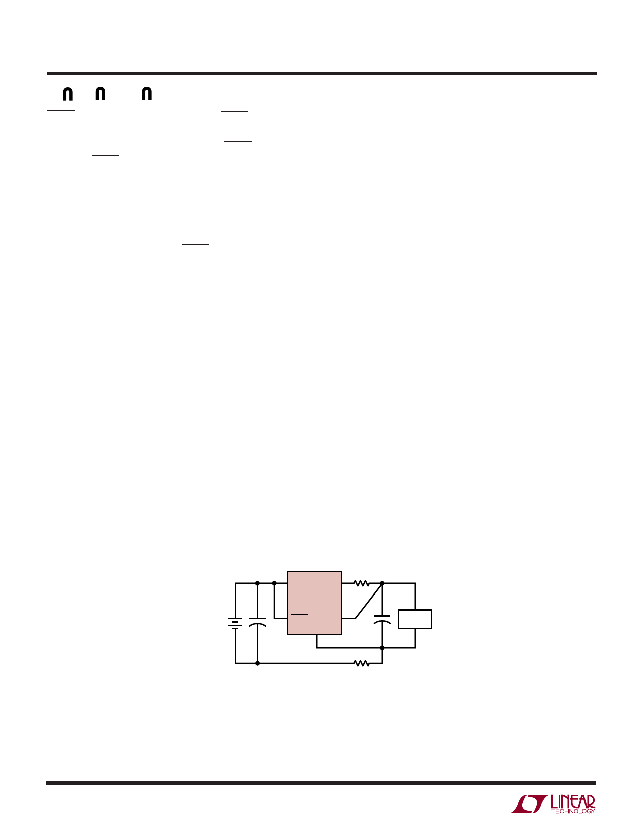
Adjustable Operation
The adjustable version of the LT1764 has an output
voltage range of 1.21V to 20V. The output voltage is set by
the ratio of two external resistors as shown in Figure 2. The
device servos the output to maintain the voltage at the ADJ
pin at 1.21V referenced to ground. The current in R1 is
then equal to 1.21V/R1 and the current in R2 is the current
in R1 plus the ADJ pin bias current. The ADJ pin bias
current, 3µA at 25°C, flows through R2 into the ADJ pin.
The output voltage can be calculated using the formula in
Figure 2. The value of R1 should be less than 4.17k to
minimize errors in the output voltage caused by the ADJ
pin bias current. Note that in shutdown the output is turned
off and the divider current will be zero.
IN
OUT
VIN
LT1764
ADJ
GND
+
R2
VOUT
R1
1764 F02
VOUT = 1.21V1+ RR21 + (IADJ)(R2)
VADJ = 1.21V
IADJ = 3µA AT 25°C
OUTPUT RANGE = 1.21V TO 20V
Figure 2. Adjustable Operation
10
The adjustable device is tested and specified with the ADJ
pin tied to the OUT pin for an output voltage of 1.21V.
Specifications for output voltages greater than 1.21V will
be proportional to the ratio of the desired output voltage to
1.21V: VOUT/1.21V. For example, load regulation for an
output current change of 1mA to 3A is – 3mV typical at
VOUT = 1.21V. At VOUT = 5V, load regulation is:
(5V/1.21V)(–3mV) = – 12.4mV
Output Capacitance and Transient Response
The LT1764 regulators are designed to be stable with a
wide range of output capacitors. The ESR of the output
capacitor affects stability, most notably with small capaci-
tors. A minimum output capacitor of 10µF with an ESR in
the range of 50mΩ to 3Ω is recommended to prevent
oscillations. Larger values of output capacitance can de-
crease the peak deviations and provide improved transient
response for larger load current changes. Bypass capaci-
tors, used to decouple individual components powered by
the LT1764-X, will increase the effective output capacitor
value.
Extra consideration must be given to the use of ceramic
capacitors. In some applications the use of ceramic ca-
pacitors with an ESR below 50mΩ can cause oscillations.
Please consult our Applications Engineering department
for help with any issues concerning the use of ceramic
output capacitors. Ceramic capacitors are manufactured
with a variety of dielectrics, each with different behavior
over temperature and applied voltage. The most common
dielectrics used are Z5U, Y5V, X5R and X7R. The Z5U and
Y5V dielectrics are good for providing high capacitances
in a small package, but exhibit strong voltage and tem-
perature coefficients as shown in Figures 3 and 4. When
used with a 5V regulator, a 10µF Y5V capacitor can exhibit
an effective value as low as 1µF to 2µF over the operating
temperature range. The X5R and X7R dielectrics result in
more stable characteristics and are more suitable for use
as the output capacitor. The X7R type has better stability
across temperature, while the X5R is less expensive and
is available in higher values.
Voltage and temperature coefficients are not the only
sources of problems. Some ceramic capacitors have a
piezoelectric response. A piezoelectric device generates
1764fa
Share Link: 