LT1764-1.5 View Datasheet(PDF) - Linear Technology
Part Name
Description
Manufacturer
LT1764-1.5 Datasheet PDF : 20 Pages
| |||
LT1764 Series
PI FU CTIO S (DD and TO-220/TSSOP)
SHDN (Pin 1/Pin 10): Shutdown. The SHDN pin is used to
put the LT1764 regulators into a low power shutdown
state. The output will be off when the SHDN pin is pulled
low. The SHDN pin can be driven either by 5V logic or
open-collector logic with a pull-up resistor. The pull-up
resistor is required to supply the pull-up current of the
open-collector gate, normally several microamperes, and
the SHDN pin current, typically 7µA. If unused, the SHDN
pin must be connected to VIN. The device will be in the low
power shutdown state if the SHDN pin is not connected.
IN (Pin 2/Pins 12, 13, 14): Input. Power is supplied to the
device through the IN pin. A bypass capacitor is required
on this pin if the device is more than six inches away from
the main input filter capacitor. In general, the output
impedance of a battery rises with frequency, so it is
advisable to include a bypass capacitor in battery-pow-
ered circuits. A bypass capacitor in the range of 1µF to
10µF is sufficient. The LT1764 regulators are designed to
withstand reverse voltages on the IN pin with respect to
ground and the OUT pin. In the case of a reverse input,
which can happen if a battery is plugged in backwards, the
device will act as if there is a diode in series with its input.
There will be no reverse current flow into the regulator and
no reverse voltage will appear at the load. The device will
protect both itself and the load.
GND (Pin 3/Pins 1, 7, 8, 9, 16, 17): Ground. The exposed
pad (FE Package) is ground and must be soldered to the
PCB for rated thermal performance.
OUT (Pin 4/Pins 3, 4, 5): Output. The output supplies
power to the load. A minimum output capacitor of 10µF is
required to prevent oscillations. Larger output capacitors
will be required for applications with large transient loads
to limit peak voltage transients. See the Applications
Information section for more information on output ca-
pacitance and reverse output characteristics.
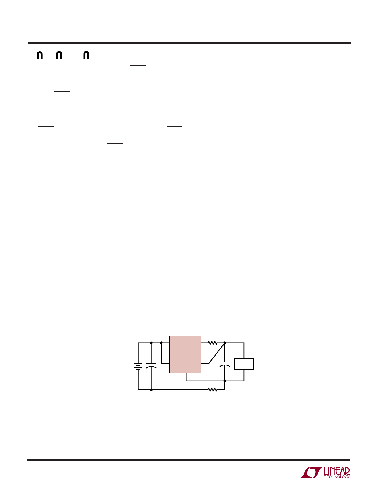
SENSE (Pin 5/Pin 6): Sense. For fixed voltage versions of
the LT1764 (LT1764-1.8/LT1764-2.5/LT1764-3.3), the
SENSE pin is the input to the error amplifier. Optimum
regulation will be obtained at the point where the SENSE
pin is connected to the OUT pin of the regulator. In critical
applications, small voltage drops are caused by the resis-
tance (RP) of PC traces between the regulator and the load.
These may be eliminated by connecting the SENSE pin to
the output at the load as shown in Figure 1 (Kelvin Sense
Connection). Note that the voltage drop across the exter-
nal PC traces will add to the dropout voltage of the
regulator. The SENSE pin bias current is 600µA at the
nominal rated output voltage. The SENSE pin can be pulled
below ground (as in a dual supply system where the
regulator load is returned to a negative supply) and still
allow the device to start and operate.
ADJ (Pin 5/Pin 6): Adjust. For the adjustable LT1764, this
is the input to the error amplifier. This pin is internally
clamped to ±7V. It has a bias current of 3µA which flows
into the pin. The ADJ pin voltage is 1.21V referenced to
ground and the output voltage range is 1.21V to 20V.
+
VIN
2
IN
4 RP
OUT
LT1764
1
5
+
SHDN SENSE
GND
3
RP
LOAD
1764 F01
Figure 1. Kelvin Sense Connection
1764fb
10
Share Link: 