LT5502 View Datasheet(PDF) - Linear Technology
Part Name
Description
Manufacturer
LT5502 Datasheet PDF : 12 Pages
| |||
LT5502
APPLICATIO S I FOR ATIO
The receive signal strength indicator (RSSI) is built into
the IF limiter. The input IF signal is detected in a current
output proportional to the IF input power. The current
outputs from two cascaded stages of IF amplifiers/limiters
are summed and converted into the RSSI voltage. The
RSSI output has an excellent linear range of 90dB. The
characteristic of RSSI output voltage versus input IF
power is independent of temperature and process varia-
tion. The nominal output impedance is 3.8kΩ. An off-chip
capacitor C7 is needed to reduce the RSSI voltage ripple.
Its value can be determined using the following formula:
C7 ≥ 1 F
760π • fIF
I/Q Demodulators
The quadrature demodulators are double balanced mix-
ers, down converting the limited IF signals from the IF
Limiter into I/Q baseband signals. The quadrature LO
carriers are obtained from the internal quadrature LO
carrier generator. The nominal output voltage of differen-
tial I/Q baseband signals is about 850mVP-P. These mag-
nitudes are well matched, and their phases are 90° apart.
Quadrature LO Carrier Generator
The quadrature LO carrier generator consists of a divide-
by-two circuit and LO buffers. An input signal (2XLO) with
twice the desired LO carrier frequency is used as the clock
for the divide-by-two circuit, producing the quadrature LO
carriers for the demodulators. The outputs are buffered
and then drive the down converting mixers. With a full
differential approach, the quadrature LO carriers are well
matched.
Integrated Low Pass Filters
The 5th order integrated lowpass filters are used for
filtering the down converted baseband outputs for both
the I-channel and the Q-channel. They serve as anti-
aliasing and pulse-shaping filters. The I/Q filters are well
matched in gain response and group delay. The 3dB
corner frequency is 7.7MHz and the group delay ripple is
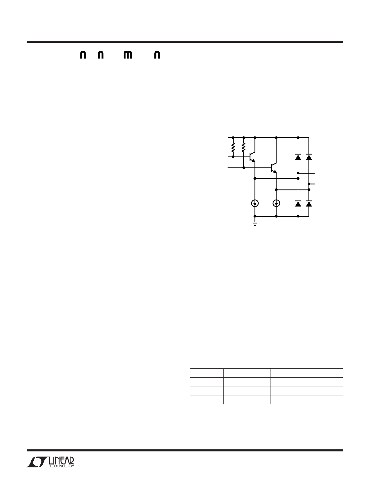
16.4ns. The I/Q differential outputs have output driving
capability of 1.5kΩ with maximum capacitive loading of
10pF. The outputs are internally biased at VCC –1.16V.
Figure 2 shows the simplified output circuit schematic of
I-channel or Q-channnel.
VCC
I-CHANNEL
(OR Q-CHANNEL):
DIFFERENTIAL
SIGNALS FROM LPF
+
200µA
–
+
200µA
–
I(OOURT+QOUT+)
I(OOURT–QOUT–)
5502 F02
Figure 2. Simplified Circuit Schematic
of I-Channel (or Q-Channel) Outputs
The I/Q baseband outputs can be directly DC-coupled to
the inputs of a baseband chip. For AC-coupled applica-
tions with large coupling capacitors, the STBY pin can be
used to prebias the outputs to the desired quiescent
voltage at much reduced current. This mode only draws
2.6mA. When the EN pin is then turned on, the chip is
quickly switched to normal operating mode without long
time constants due to charging or discharging the large
coupling capacitors. Table 2 shows the logic of the EN pin
and STBY pin. In both normal operating mode and standby
mode, the maximum discharging current is about 200µA,
and the maximum charging current is more than 10mA.
Table 2. The logic of different operating modes
EN
STBY
Comments
Low
Low
Shutdown Mode
Low
High
Standby Mode
High
Low or High
Normal Operation Mode
7
Share Link: 