LTC1346A(RevA) View Datasheet(PDF) - Linear Technology
Part Name
Description
Manufacturer
LTC1346A Datasheet PDF : 12 Pages
| |||
LTC1346A
AC ELECTRICAL CHARACTERISTICS The ● denotes specifications which apply over the full operating
temperature range. VCC = 5V ±5%, VEE = – 5V ±5% (Note 2)
SYMBOL PARAMETER
CONDITIONS
MIN
ICC
IEE
tr, tf
tPLH
tPHL
tSKEW
tPLH
tPHL
tSKEW
tZL
VCC Supply Current
VOS = 0V, S0 = Low, S1 = S2 = High (Figure 1) ●
No Load, S0 = Low, S1 = S2 = High
●
Shutdown, S0 = VCC, S1 = S2 = 0V
●
VEE Supply Current
VOS = 0V, S0 = Low, S1 = S2 = High (Figure 1) ●
No Load, S0 = Low, S1 = S2 = High
●
Shutdown, S0 = VCC, S1 = S2 = 0V
●
Transmitter Rise or Fall Time
VOS = 0V (Figures 1, 3)
●
Transmitter Input to Output
VOS = 0V (Figures 1, 3)
●
Transmitter Input to Output
VOS = 0V (Figures 1, 3)
●
Transmitter Output to Output
VOS = 0V (Figures 1, 3)
Receiver Input to Output
VOS = 0V (Figures 1, 4)
●
Receiver Input to Output
VOS = 0V (Figures 1, 4)
●
Differential Receiver Skew, tPLH – tPHL
VOS = 0V (Figures 1, 4)
Receiver Enable to Output Low (Active Mode) CL = 15pF, SW1 Closed (Figures 2, 5)
●
Receiver Enable to Output Low
(from Shutdown, Note 3)
CL = 15pF, SW1 Closed (Figures 2, 5)
tZH
Receiver Enable to Output High (Active Mode) CL = 15pF, SW2 Closed (Figures 2, 5)
●
Receiver Enable to Output High
(from Shutdown, Note 3)
CL = 15pF, SW2 Closed (Figures 2, 5)
tLZ
Receiver Disable from Low
tHZ
Receiver Disable from High
CL = 15pF, SW1 Closed (Figures 2, 5)
●
CL = 15pF, SW2 Closed (Figures 2, 5)
●
TYP MAX UNITS
40
50
mA
6
9
mA
0.1
100
µA
– 40 – 50
mA
–6
–9
mA
– 0.1 – 100
µA
7
40
ns
25
70
ns
30
70
ns
5
ns
50
100
ns
55
100
ns
5
ns
40
70
ns
2
µs
35
70
ns
2
µs
30
70
ns
35
70
ns
Note 1: The Absolute Maximum Ratings are those values beyond which
the life of a device may be impaired.
Note 2: All currents into device pins are positive; all currents out of device
pins are termed negative. All voltages are referenced to device ground
unless otherwise specified.
Note 3: Receiver enable to output valid high or low from Shutdown is
typically 2µs.
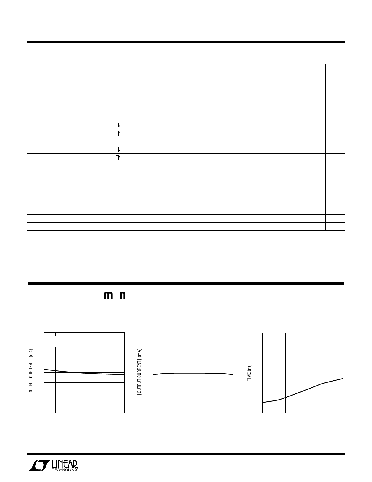
TYPICAL PERFOR A CE CHARACTERISTICS
Transmitter Output Current
vs Temperature
13
VCC = 5V
VEE = –5V
12
11
10
9
–50 –25
0 25 50 75
TEMPERATURE (˚C)
100 125
1346A G01
Transmitter Output Current
vs Output Voltage
13
TA = 25°C
VCC = 5V
VEE = –5V
12
11
10
9
–2.0 –1.5 –1.0 –0.5 0 0.5 1.0 1.5 2.0
OUTPUT VOLTAGE (V)
1346A G02
Transmitter Output Skew
vs Temperature
20
VCC = 5V
VEE = –5V
15
10
5
0
–50 –25
0 25 50 75
TEMPERATURE (˚C)
100 125
1346A G03
1346afa
3
Share Link: 