LTC1696HS6 View Datasheet(PDF) - Linear Technology
Part Name
Description
Manufacturer
LTC1696HS6 Datasheet PDF : 14 Pages
| |||
LTC1696
ABSOLUTE MAXIMUM RATINGS
(Note 1)
Supply Voltage (VCC).................................................28V
Input Voltage
FB1, FB2................................................ – 0.3V to 17V
TIMER/RESET......................................... –0.3V to 17V
Operating Junction Temperature Range (Note 2)
LTC1696E............................................ –40°C to 125°C
LTC1696I............................................ –40°C to 125°C
LTC1696H........................................... –40°C to 150°C
Storage Temperature Range.................... –65°C to 150°C
Lead Temperature (Soldering, 10 sec)................... 300°C
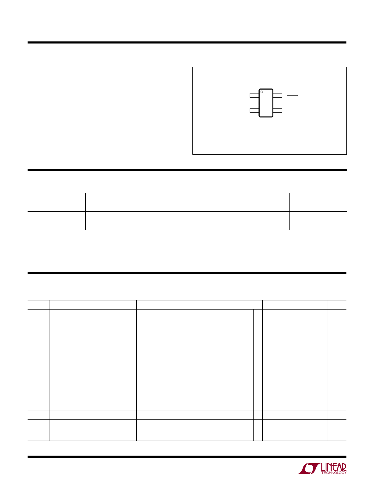
PIN CONFIGURATION
FB1 1
GND 2
VCC 3
TOP VIEW
6
TIMER/
RESET
5 FB2
4 OUT
S6 PACKAGE
6-LEAD PLASTIC TSOT-23
TJMAX = 150°C, θJA = 192°C/W
ORDER INFORMATION
LEAD FREE FINISH
TAPE AND REEL
PART MARKING
PACKAGE DESCRIPTION
TEMPERATURE RANGE
LTC1696ES6#PBF
LTC1696ES6#TRPBF
LTLT
6-Lead Plastic TSOT-23
–40°C to 125°C
LTC1696IS6#PBF
LTC1696IS6#TRPBF
LTLT
6-Lead Plastic TSOT-23
–40°C to 125°C
LTC1696HS6#PBF
LTC1696HS6#TRPBF
LTLT
6-Lead Plastic TSOT-23
–40°C to 150°C
Consult LTC Marketing for parts specified with wider operating temperature ranges. *The temperature grade is identified by a label on the shipping container.
Consult LTC Marketing for information on nonstandard lead based finish parts.
For more information on lead free part marking, go to: http://www.linear.com/leadfree/
For more information on tape and reel specifications, go to: http://www.linear.com/tapeandreel/
ELECTRICAL CHARACTERISTICS The l denotes the specifications which apply over the specified operating
junction temperature range, otherwise specifications are at TA = 25°C. 2.7V ≤ VCC ≤ 27V (Notes 2, 3, 4) unless otherwise noted.
SYMBOL PARAMETER
CONDITIONS
MIN TYP MAX UNITS
VCC
Supply Voltage Range
IVCC
Standby Supply Current
Active Supply Current
VFB
FB1, FB2 Feedback Threshold
IFB
VFBHST
VLKO
FB1, FB2 Input Current
FB1, FB2 Feedback Hysteresis
VCC Undervoltage Lockout
Low-to-High Transition
High-to-Low Transition
Operating Range
● 2.7
27
V
FB1, FB2 < VFB
●
170
540
µA
FB1, FB2 > VFB, COUT = 1000pF
●
1.1
3.5
mA
Voltage Going Positive TA ≥ 0°C and TA ≤ 85°C
● 0.862 0.880 0.898
V
TA ≥ 0°C and TA ≤ 125°C
● 0.858 0.880 0.898
V
TA ≥ 0°C and TA ≤ 150°C
● 0.853 0.880 0.898
V
TA < 0°C
● 0.853 0.880 0.907
V
● –1 – 0.05
µA
High-to-Low Transition
12
mV
FB1, FB2 > VFB
● 1.75 2.05 2.35
V
● 1.64 1.94 2.24
V
VLKH
VCC Undervoltage Lockout Hysteresis FB1, FB2 > VFB
VRST
TIMER/RESET Reset Low Threshold FB1, FB2 > VFB
VTIM
TIMER/RESET Timer High Threshold FB1, FB2 > VFB, TA ≤ 85°C
TA ≤ 125°C
TA ≤ 150°C
110
mV
● 0.78 0.865 0.95
V
● 1.11 1.185 1.26
V
● 1.08 1.185 1.26
V
● 1.07 1.185 1.26
V
1696fb
2
For more information www.linear.com/LTC1696
Share Link: 