LTC6907HS6 View Datasheet(PDF) - Linear Technology
Part Name
Description
Manufacturer
LTC6907HS6 Datasheet PDF : 12 Pages
| |||
LTC6907
APPLICATIO S I FOR ATIO
Selecting RSET and the Divider Ratio
The LTC6907 contains a master oscillator followed by a
digital divider (see Block Diagram). RSET determines the
master oscillator frequency and the three level DIV pin sets
the divider ratio, N. The range of frequencies accessible in
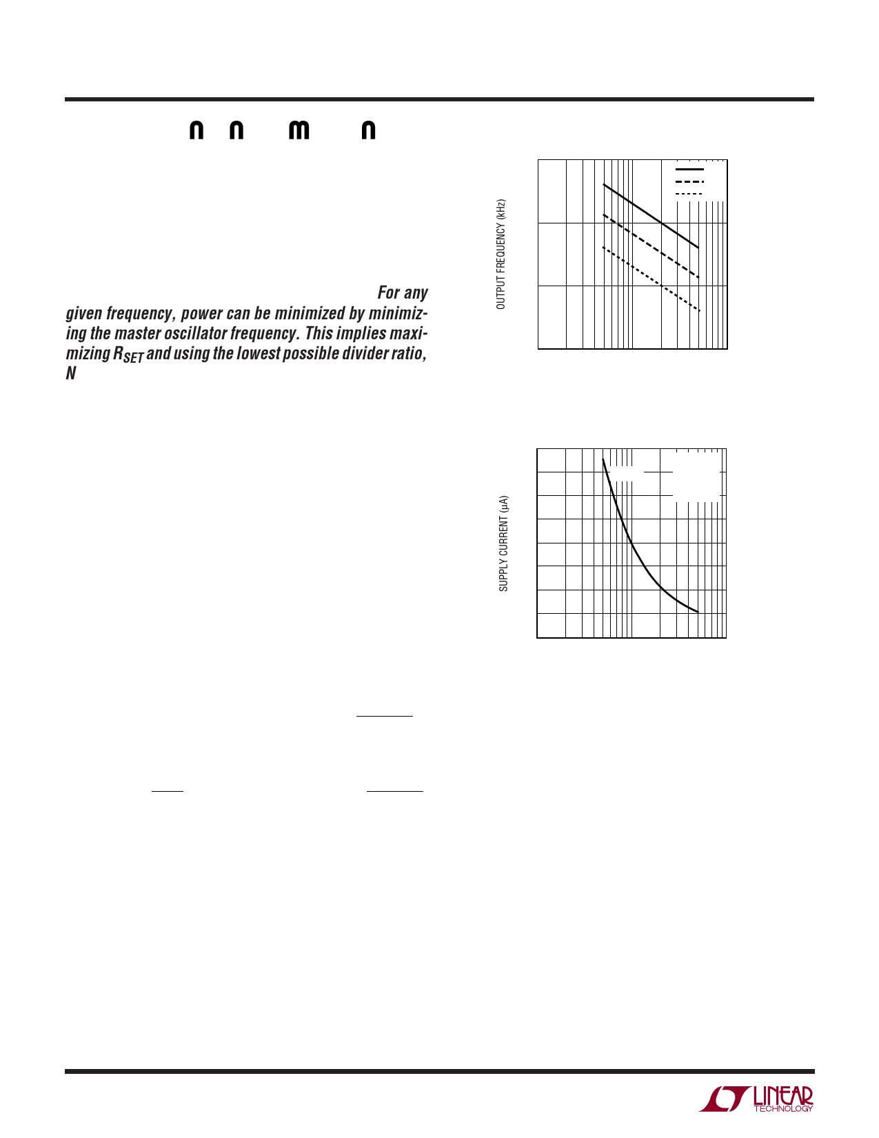
each divider ratio overlap, as shown in Figure 7. This
figure is derived from the equations in Table 1. For any
given frequency, power can be minimized by minimiz-
ing the master oscillator frequency. This implies maxi-
mizing RSET and using the lowest possible divider ratio,
N. The relationship between RSET, N and the unloaded
power consumption is shown in Figure 8. The supply
current decreases for large values of RSET. Refer to the
section titled “Jitter and Divide Ratio.”
Minimizing Power Consumption
The supply current of the LTC6907 has four current
components:
• Constant (Independent V+, ƒOUT and CLOAD)
• Proportional to ISET (which is the current in RSET)
• Proportional to V+, ƒOUT and CLOAD
• Proportional to V+ and RLOAD
An approximate expression for the total supply current is:
( ) I+ ≅ 7µA + 6 •ISET + V+ • ƒOUT •
CLOAD + 5pF
+ V+
2 • RLOAD
or, in terms of VSET,
( ) I+
≅
7µA
+
6
•
VSET
RSET
+
V+
•
ƒOUT
•
CLOAD + 5pF
+ V+
2 • RLOAD
VSET is approximately 650mV at 25°C, but varies with
temperature. This behavior is shown in the Typical Perfor-
mance Characteristics.
Power can be minimized by maximizing RSET, minimizing
the load on the OUT pin and operating at lower frequen-
cies. Figure 9 shows total supply current vs frequency
under typical conditions. Below 100kHz the load current is
negligible for the 5pF load shown.
8
10000
÷1
÷3
÷10
1000
100
10
10
100
RSET (kΩ)
1000
6907 F07
Figure 7. RSET vs Desired Output Frequency
160
140
ISUPPLY
CVL+O=A3DV= 0
DIV = –: 1
120
TA = 25°C
100
80
60
40
20
0
10
100
1000
RSET (kΩ)
6907 F08
Figure 8. Unloaded Supply Current vs RSET
Guarding Against PC Board Leakage
The LTC6907 uses relatively large resistance values for
RSET to minimize power consumption. For RSET = 500k,
the SET pin current is typically only 13µA. Thus, only 13nA
leaking into the SET pin causes a 0.1% frequency error.
Similarly, 500M of leakage resistance across RSET
(1000 • RSET) causes the same 0.1% error.
Achieving the highest accuracy requires controlling po-
tential leakage paths. PC board leakage is aggravated by
both dirt and moisture. Effective cleaning is a good first
step to minimizing leakage.
Another effective method for controlling leakage is to shunt
the leakage current away from the sensitive node through
a low impedance path. The LTC6907 provides a signal on
the GRD pin for this purpose. Figure 10 shows a PC board
6907fa
Share Link: 