LXM1614 View Datasheet(PDF) - Microsemi Corporation
Part Name
Description
Manufacturer
LXM1614 Datasheet PDF : 9 Pages
| |||
A MICROSEMI COMPANY
RangeMAX™
LXM1614-14-11
DUAL DIMMING, EXTENDED TEMPEERATURE CCFL INVERTER MODULE
PRELIMINARY DATASHEET
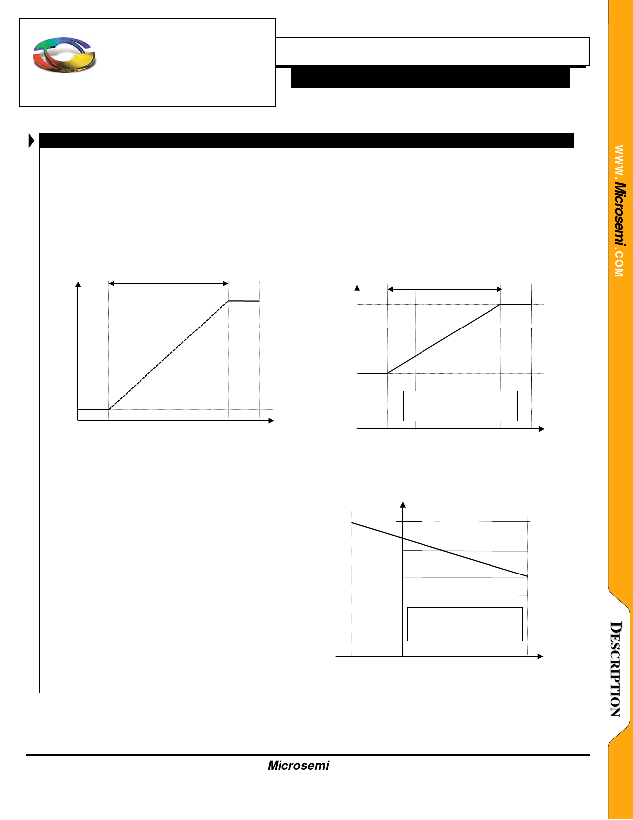
WIDE RANGE DIMMING FUNCTION
Dimming can be controlled by a DC voltage (like a voltage
output DAC) or by a PWM signal (5V logic level PWM signal
from a micro controller). The PWM signal should be 400Hz to
4kHz, 0V to 5V, 0% to 100% duty cycle.
Brightness
100%
control range
AMPLITUDE BOOST FUNCTION
The Boost Function Control signal levels are the same as
the Dimming Control. Less than 0.5V provides 4mA
maximum lamp current while 4.5V on Boost provides “max
boost” with a max lamp current of 9mA. Please note that
these maximum lamp current levels are protected by the on-
board thermister which limits the maximum lamp current
automatically as a function of temperature as seen in Figure
9.
Lamp Current (mArms)
control range
boost mode
9
VIN = 9V
1%
BRITE
0.0 V 0.5 V
4.5 V 5.0 V
- Brightness as a function of the BRITE control (CN1-7)
4
no boost mode
Typical curve for 5.8” panel. Other
panels may be different.
0.0 0.5
IBOOST
4.5 5.0
– Maximum lamp current as a function of the Boost control
(CN1-6)
Lamp Current (mArms)
9.0
7.5
VIN = 9V
5.5
4.0
Typical curve for 5.8” panel.
Other panels may be different.
Temp
-40
0
25
85°C
– Maximum lamp current as a function of ambient
temperature
Copyright © 2000
Rev. 0.3b,2000-11-20
Microsemi
Linfinity Microelectronics Division
11861 Western Avenue, Garden Grove, CA. 92841, 714-898-8121, Fax: 714-893-2570
Page 8
Share Link: 