M1025-1Z-167.2820 View Datasheet(PDF) - Integrated Circuit Systems
Part Name
Description
Manufacturer
M1025-1Z-167.2820 Datasheet PDF : 14 Pages
| |||
Integrated
Circuit
Systems, Inc.
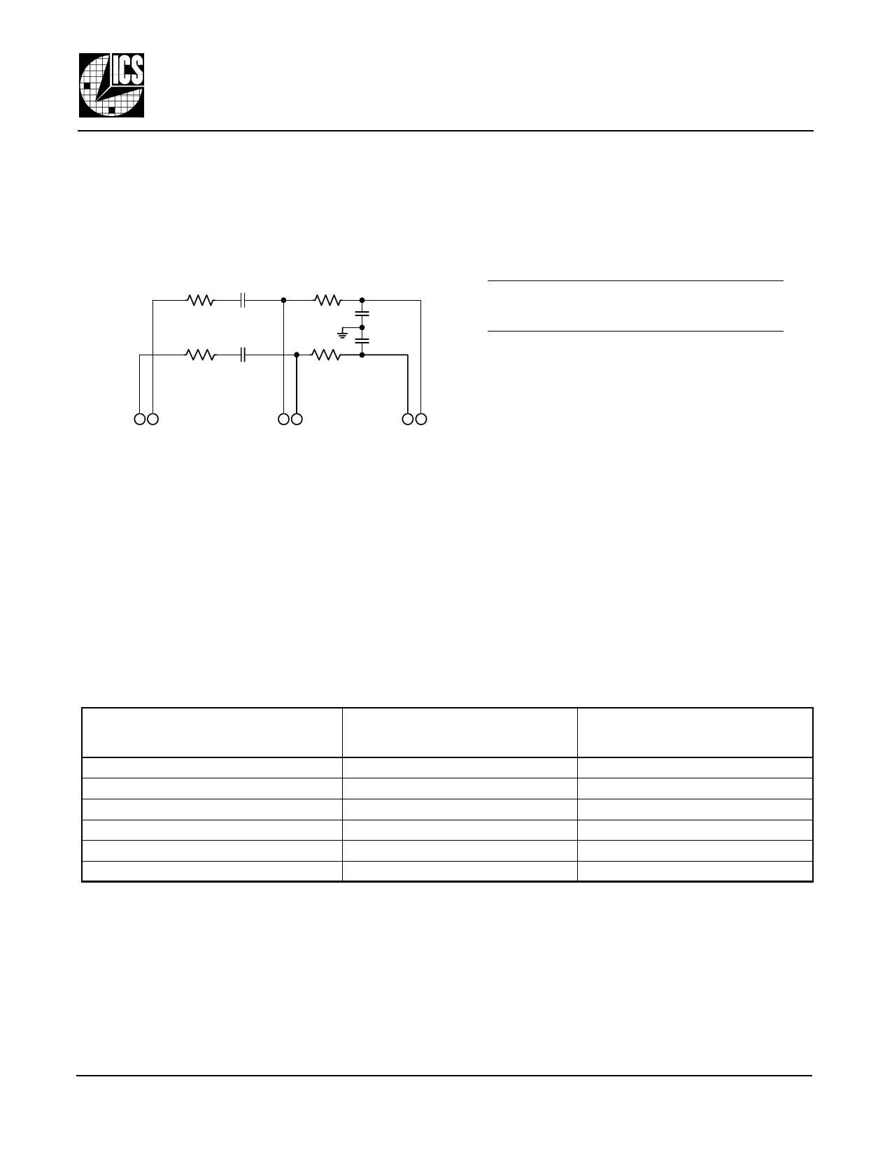
External Loop Filter
To provide stable PLL operation, the M1025/26 requires
the use of an external loop filter. This is provided via the
provided filter pins (see Figure 5).
Due to the differential signal path design, the
implementation requires two identical complementary
RC filters as shown here.
RLOOP CLOOP
RPOST
RLOOP CLOOP
RPOST
CPOST
CPOST
M1025/26
VCSO BASED CLOCK PLL WITH AUTOSWITCH
Product Data Sheet
PLL Simulator Tool Available
A free PC software utility is available on the ICS website
(www.icst.com). The M2000 Timing Modules PLL
Simulator is a downloadable application that simulates
PLL jitter and wander transfer characteristics. This
enables the user to set appropriate external loop
component values in a given application.
For guidance on device or loop filter implementa-
tion, contact CMBU (Commercial Business Unit)
Product Applications at (508) 852-5400.
OP_IN nOP_IN
49
OP_OUT nOP_OUT
85
Figure 5: External Loop Filter
nVC VC
67
See Table 7, Example External Loop Filter Component
Values, below.
PLL Bandwidth is affected by loop filter component
values, the “M” value, and the “PLL Loop Constants”
listed in AC Characteristics on pg. 12.
The MR_SEL3:0 settings can be used to actively change
PLL loop bandwidth in a given application. See “M and
R Divider Look-Up Tables (LUT)” on pg. 3.
Example External Loop Filter Component Values1
for M1025-yz-155.5200 and M1026-yz-155.5200
VCSO Parameters: KVCO = 200kHz/V, RIN = 100kΩ (pin NBW = 0), VCSO Bandwidth = 700kHz.
Device Configuration
Example External Loop Filter Comp. Values Nominal Performance Using These Values
FREF
(MHz)
19.44 2
FVCSO MR_SEL3:0 MDiv NBW
(MHz)
155.52 0 0 0 0 8 0
RLOOP
6.8kΩ
CLOOP
10µF
RPOST
82kΩ
CPOST
1000pF
PLL Loop
Bandwidth
315Hz
Damping Passband
Factor Peaking (dB)
5.4
0.068
38.88 3 155.52 0 0 0 1 16 0
12kΩ 10µF 82kΩ 1000pF
270Hz
6.7
0.044
77.76 4 155.52 0 1 0 1 8 0 6.8kΩ 10µF 82kΩ 1000pF
315Hz
5.4
0.068
77.76 5 155.52 0 1 1 0 32 0
22kΩ 4.7µF 82kΩ 1000pF
250Hz
6.0
0.05
155.52 4 155.52 1 0 1 0 16 0
12kΩ 10µF 82kΩ 1000pF
270Hz
6.7
0.044
155.52 5 155.52 1 0 1 1 64 0
47kΩ 2.2µF 82kΩ 1000pF
266Hz
6.2
0.05
Table 7: Example External Loop Filter Component Values
Note 1: KVCO , VCSO Bandwidth, M Divider Value, and External Loop Filter Component Values determine Loop Bandwidth, Damping Factor,
and Passband Peaking. For PLL Simulator software, go to www.icst.com.
Note 2: This row is for the M1025 only.
Note 3: This row is for the M1026 only.
Note 4: Optimal for system clock filtering.
Note 5: Optimal for loop timing mode (LOL, AutoSwitch, or Hitless Switching should not be used).
M1025/26 Datasheet Rev 1.0
9 of 14
Revised 28Jul2004
Integrated Circuit Systems, Inc. ● Networking & Communications ● www.icst.com ● tel (508) 852-5400
Share Link: 