MAX6658 View Datasheet(PDF) - Maxim Integrated
Part Name
Description
Manufacturer
MAX6658
Maxim Integrated

MAX6658 Datasheet PDF : 16 Pages
| |||
±1°C, SMBus-Compatible Remote/Local Temperature
Sensors with Overtemperature Alarms
surements. The noise can be reduced with careful PC
board layout and proper external noise filtering.
High-frequency EMI is best filtered at DXP and DXN
with an external 2200pF capacitor. Larger capacitor
values can be used for added filtering, but do not
exceed 3300pF because it can introduce errors due to
the rise time of the switched current source.
10MILS
10MILS
GND
10MILS
DXP
MINIMUM
DXN
10MILS
GND
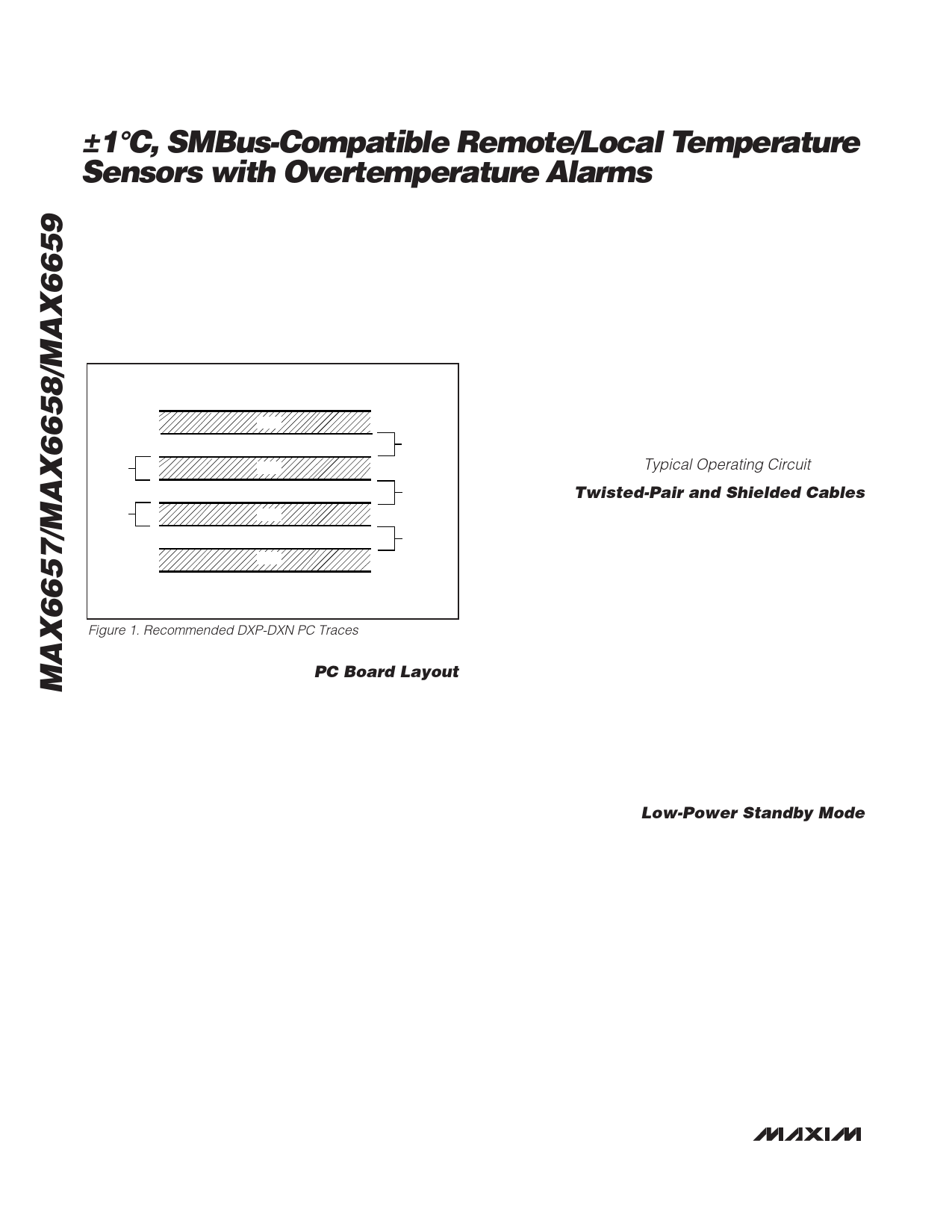
Figure 1. Recommended DXP-DXN PC Traces
PC Board Layout
Follow these guidelines to reduce the measurement
error of the temperature sensors:
1) Place the MAX6657/MAX6658/MAX6659 as close
as is practical to the remote diode. In noisy environ-
ments, such as a computer motherboard, this dis-
tance can be 4in to 8in (typ). This length can be
increased if the worst noise sources are avoided.
Noise sources include CRTs, clock generators,
memory buses, and ISA/PCI buses.
2) Do not route the DXP-DXN lines next to the deflec-
tion coils of a CRT. Also, do not route the traces
across fast digital signals, which can easily intro-
duce +30°C error, even with good filtering.
3) Route the DXP and DXN traces in parallel and in
close proximity to each other, away from any higher
voltage traces, such as +12VDC. Leakage currents
from PC board contamination must be dealt with
carefully since a 20M⊠leakage path from DXP to
ground causes about +1°C error. If high-voltage
traces are unavoidable, connect guard traces to GND
on either side of the DXP-DXN traces (Figure 1).
4) Route through as few vias and crossunders as pos-
sible to minimize copper/solder thermocouple
effects.
5) When introducing a thermocouple, make sure that
both the DXP and the DXN paths have matching
thermocouples. A copper-solder thermocouple
exhibits 3”V/°C, and it takes about 200”V of voltage
error at DXP-DXN to cause a +1°C measurement
error. Adding a few thermocouples causes a negli-
gible error.
6) Use wide traces. Narrow traces are more inductive
and tend to pick up radiated noise. The 10mil widths
and spacings that are recommended in Figure 1 are
not absolutely necessary, as they offer only a minor
improvement in leakage and noise over narrow
traces. Use wider traces when practical.
7) Add a 200⊠resistor in series with VCC for best
noise filtering (see Typical Operating Circuit).
Twisted-Pair and Shielded Cables
Use a twisted-pair cable to connect the remote sensor
for remote-sensor distances longer than 8in or in very
noisy environments. Twisted-pair cable lengths can be
between 6ft and 12ft before noise introduces excessive
errors. For longer distances, the best solution is a
shielded twisted pair like that used for audio micro-
phones. For example, Belden #8451 works well for dis-
tances up to 100ft in a noisy environment. At the
device, connect the twisted pair to DXP and DXN and
the shield to GND. Leave the shield unconnected at the
remote sensor.
For very long cable runs, the cableâs parasitic capaci-
tance often provides noise filtering, so the 2200pF
capacitor can often be removed or reduced in value.
Cable resistance also affects remote-sensor accuracy.
For every 1⊠of series resistance, the error is approxi-
mately +1/2°C.
Low-Power Standby Mode
Standby mode reduces the supply current to less than
10”A by disabling the ADC. Enter hardware standby
(MAX6659 only) by forcing the STBY pin low, or enter
software standby by setting the RUN/STOP bit to 1 in
the Configuration Byte register. Hardware and software
standbys are very similarâall data is retained in memo-
ry, and the SMB interface is alive and listening for
SMBus commands. The only difference is that in soft-
ware standby mode, the one-shot command initiates a
conversion. With hardware standby, the one-shot com-
mand is ignored. Activity on the SMBus causes the
device to draw extra supply current.
Driving the STBY pin low overrides any software con-
version command. If a hardware or software standby
command is received while a conversion is in progress,
the conversion cycle is interrupted, and the tempera-
8 _______________________________________________________________________________________
Share Link: