MAX9741 View Datasheet(PDF) - Maxim Integrated
Part Name
Description
Manufacturer
MAX9741 Datasheet PDF : 16 Pages
| |||
12W+12W, Low-EMI, Spread-Spectrum,
Stereo, Class D Amplifier
Internal Regulator
The MAX9741 has an internal linear regulator, REG,
used to power the internal analog circuitry. The voltage
at REG is nominally 6V. Bypass REG to AGND with a
10nF capacitor, rated for at least 10V. REG is turned off
in shutdown.
Applications Information
Class D Amplifier Outputs
Class D amplifiers differ from analog amplifiers such as
Class AB in that their output waveform is composed of
high-frequency pulses from ground to the supply rail.
When viewed with an oscilloscope the audio signal will
not be seen; instead, the high-frequency pulses domi-
nate. To evaluate the output of a Class D amplifier
requires taking the difference from the positive and
negative outputs, then lowpass filtering the difference
to recover the amplified audio signal.
Ferrite Bead Output Filters
The MAX9741’s low-EMI output switching method
reduces the output filtering requirements when compared
to pure PWM Class D amplifiers. The outputs will contain
both differential and common-mode noise at the switch-
ing frequency and its harmonics. In many applications,
a simple ferrite bead filter (see the Simplified Block
Diagram) will allow the amplifier to pass FCC EMI limits.
Ferrite beads offer significant cost and size reductions
when compared to conventional inductors. The ferrite
bead type and capacitor value can be adjusted to tune
the rejection to match the speaker cable length.
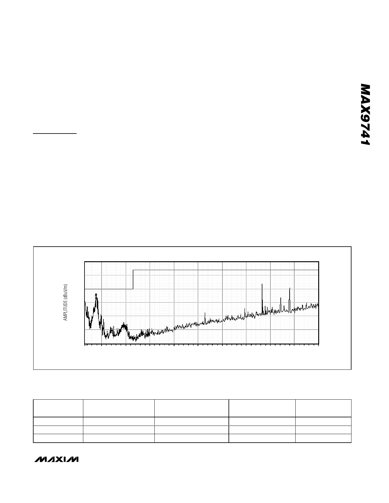
Actual EMI test results for the MAX9741 are shown in
Figure 3. This shows the MAX9741, tested in a 10m ane-
choic EMC chamber. The MAX9741 test conditions
were: SSM mode, 0.5m cables on each side, 16dB gain,
18V supply voltage, both channels playing pink noise at
4W per channel into 8Ω shielded speakers.
The graph of Figure 3 indicates peak readings. Actual
quasi peak readings per EN55022B specification will
be lower due to Maxim’s proprietary SSM mode. Table
2 lists select values, indicating the peak reading, the
quasi-peak reading, and the actual margin to
EN55022B specification.
40
35
30
25
20
15
10
30
100
200
300
400
500
600
FREQUENCY (MHz)
Figure 3. EMI Measurement of MAX9741 in 10m Anechoic Chamber
Table 2. Peak and Quasi-Peak EMI Readings
FREQUENCY
(MHz)
75.38
78.57
83.18
PRELIMINARY PEAK
READING (dBµV/m)
28.1
28.0
26.6
QUASI PEAK READING
(dBµV/m)
18.3
21.9
20.6
700
800
900
1000
EN55022B LIMIT
(dBµV/m)
30.0
30.0
30.0
ACTUAL MARGIN
(dBµV/m)
11.7
-8.1
-9.4
_______________________________________________________________________________________ 9
Share Link: 