MB90385(2008) View Datasheet(PDF) - Fujitsu
Part Name
Description
Manufacturer
MB90385 Datasheet PDF : 84 Pages
| |||
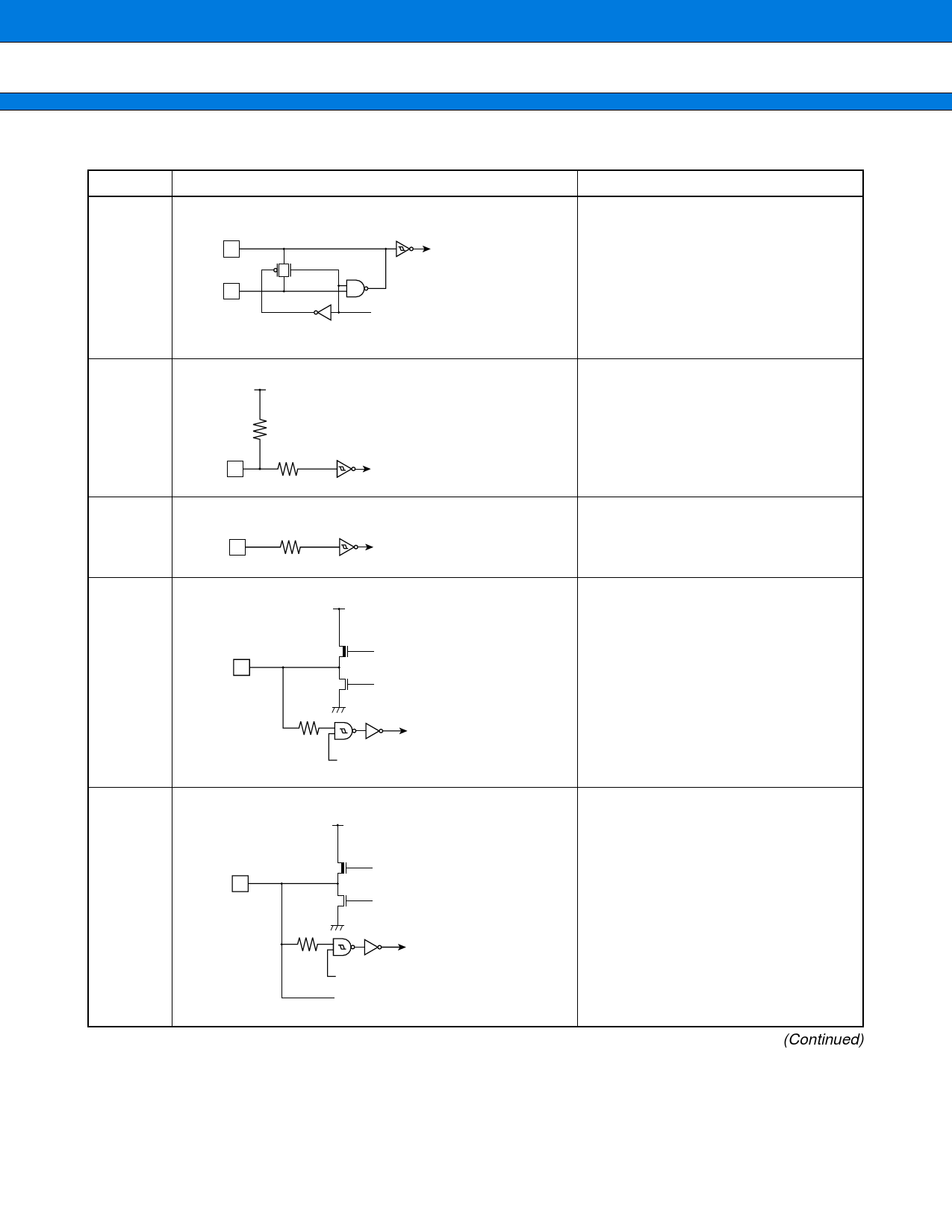
■ I/O CIRCUIT TYPE
Type
A
X1
X1A
X0
X0A
Circuit
Clock input
Standby control signal
B
Vcc
R
R
Hysteresis input
C
R
Hysteresis input
D
Vcc
P-ch Digital output
Digital output
N-ch
R
Vss
CMOS
hysteresis input
Standby control
E
Vcc
P-ch Digital output
Digital output
N-ch
R
Vss
CMOS
hysteresis input
Standby control
Analog input
MB90385 Series
Remarks
• High-rate oscillation feedback
resistor, approx.1 MΩ
• Low-rate oscillation feedback
resistor, approx.10 MΩ
• Hysteresis input with pull-up
resistor.
• Pull-up resistor, approx.50 kΩ
• Hysteresis input
• CMOS hysteresis input
• CMOS level output
• Standby control provided
• CMOS hysteresis input
• CMOS level output
• Shared for analog input pin
• Standby control provided
(Continued)
DS07-13717-5E
9
Share Link: 