MBM29F080A-70PF View Datasheet(PDF) - Fujitsu
Part Name
Description
Manufacturer
MBM29F080A-70PF Datasheet PDF : 47 Pages
| |||
To Top / Lineup / Index
MBM29F080A-55/-70/-90
Temporary Sector Group Unprotection
This feature allows temporary unprotection of previously protected sector groups of the MBM29F080A device
in order to change data. The Sector Group Unprotection mode is activated by setting the RESET pin to high
voltage (12 V). During this mode, formerly protected sector groups can be programmed or erased by selecting
the sector group addresses. Once the 12 V is taken away from the RESET pin, all the previously protected sector
groups will be protected again. Refer to Figures 14 and 21.
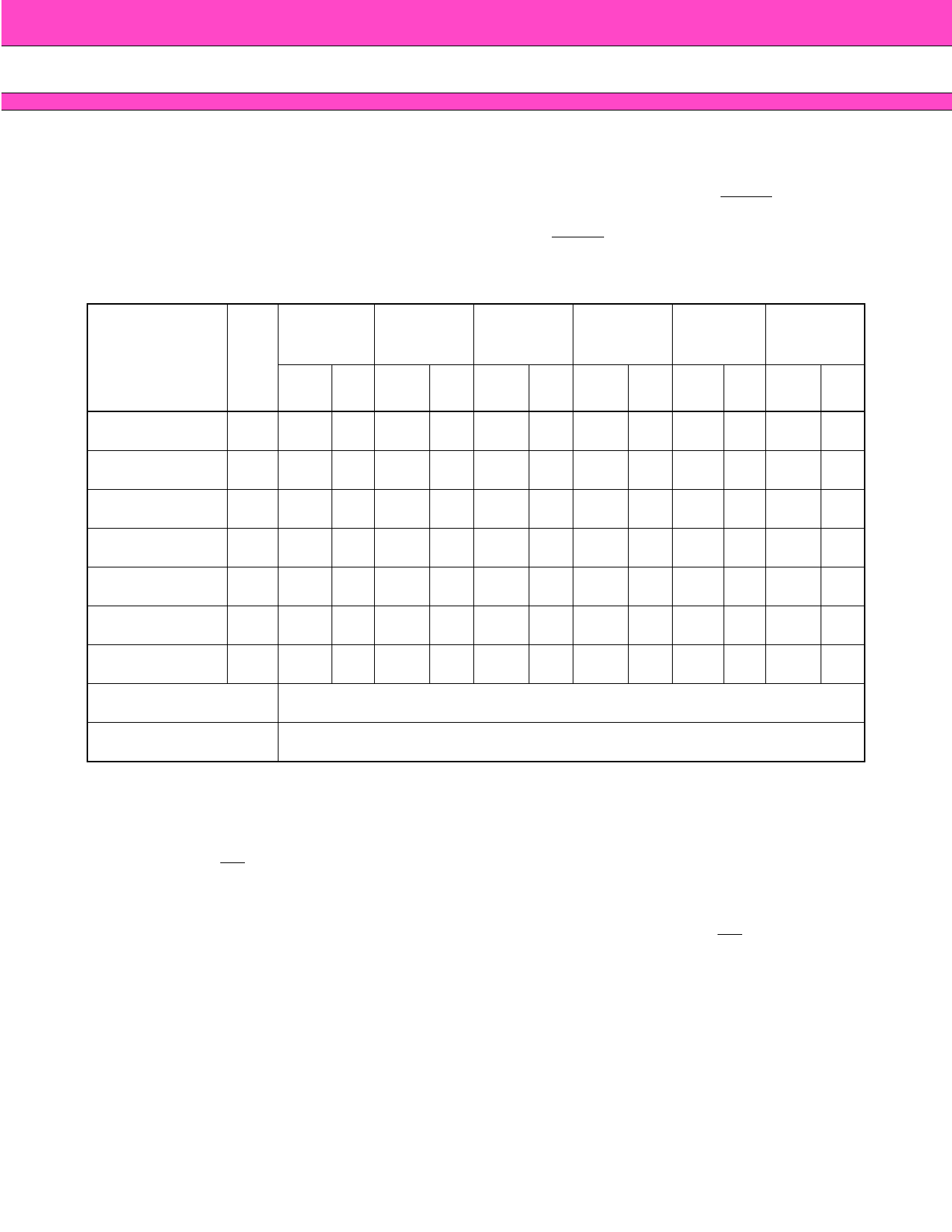
Table 6 MBM29F080A Command Definitions
Command
Sequence
Bus
Write
First Bus Second Bus Third Bus
Write Cycle Write Cycle Write Cycle
Fourth Bus
Read/Write
Cycle
Fifth Bus
Write
Cycle
Cycles
Req'd
Addr. Data
Addr.
Data
Addr.
Data
Addr.
Data Addr.
Dat
a
Sixth Bus
Write Cycle
Addr. Data
Read/Reset*
1 XXXH F0H вҖ” вҖ” вҖ” вҖ” вҖ” вҖ” вҖ” вҖ” вҖ” вҖ”
Reset/Read*
3 555H AAH 2AAH 55H 555H F0H RA RD вҖ” вҖ” вҖ” вҖ”
Manufacture Code 3 555H AAH 2AAH 55H 555H 90H 00H 04H вҖ” вҖ” вҖ” вҖ”
Device Code
3 555H AAH 2AAH 55H 555H 90H 01H 05H вҖ” вҖ” вҖ” вҖ”
Byte Program
4 555H AAH 2AAH 55H 555H A0H PA PD вҖ” вҖ” вҖ” вҖ”
Chip Erase
6 555H AAH 2AAH 55H 555H 80H 555H AAH 2AAH 55H 555H 10H
Sector Erase
6 555H AAH 2AAH 55H 555H 80H 555H AAH 2AAH 55H SA 30H
Sector Erase Suspend Erase can be suspended during sector erase with Addr (вҖңHвҖқ or вҖңLвҖқ), Data (B0H)
Sector Erase Resume Erase can be resumed after suspend with Addr (вҖңHвҖқ or вҖңLвҖқ), Data (30H)
Notes: 1. Address bits A11 to A19 = X = вҖңHвҖқ or вҖңLвҖқ for all address commands except or Program Address (PA) and
Sector Address (SA).
2. Bus operations are defined in Table 2.
3. RA = Address of the memory location to be read.
PA = Address of the memory location to be programmed. Addresses are latched on the falling edge of
the WE pulse.
SA = Address of the sector to be erased. The combination of A19, A18, A17, and A16 will uniquely select
any sector.
4. RD = Data read from location RA during read operation.
PD = Data to be programmed at location PA. Data is latched on the rising edge of WE.
5. Read and Byte program functions to non-erasing sectors are allowed in the Erase Suspend mode.
6. The system should generate the following address pattens: 555H or 2AAH to addresses A0 to A10.
*: Either of the two reset commands will reset the device.
Command Definitions
Device operations are selected by writing specific address and data sequences into the command register.
Writing incorrect address and data values or writing them in the improper sequence will reset the device to the
read mode. Table 6 defines the valid register command sequences. Note that the Erase Suspend (B0H) and
Erase Resume (30H) commands are valid only while the Sector Erase operation is in progress. Moreover, both
Read/Reset commands are functionally equivalent, resetting the device to the read mode.
13
Share Link: 