MC13109A View Datasheet(PDF) - Motorola => Freescale
Part Name
Description
Manufacturer
MC13109A Datasheet PDF : 28 Pages
| |||
MC13109A
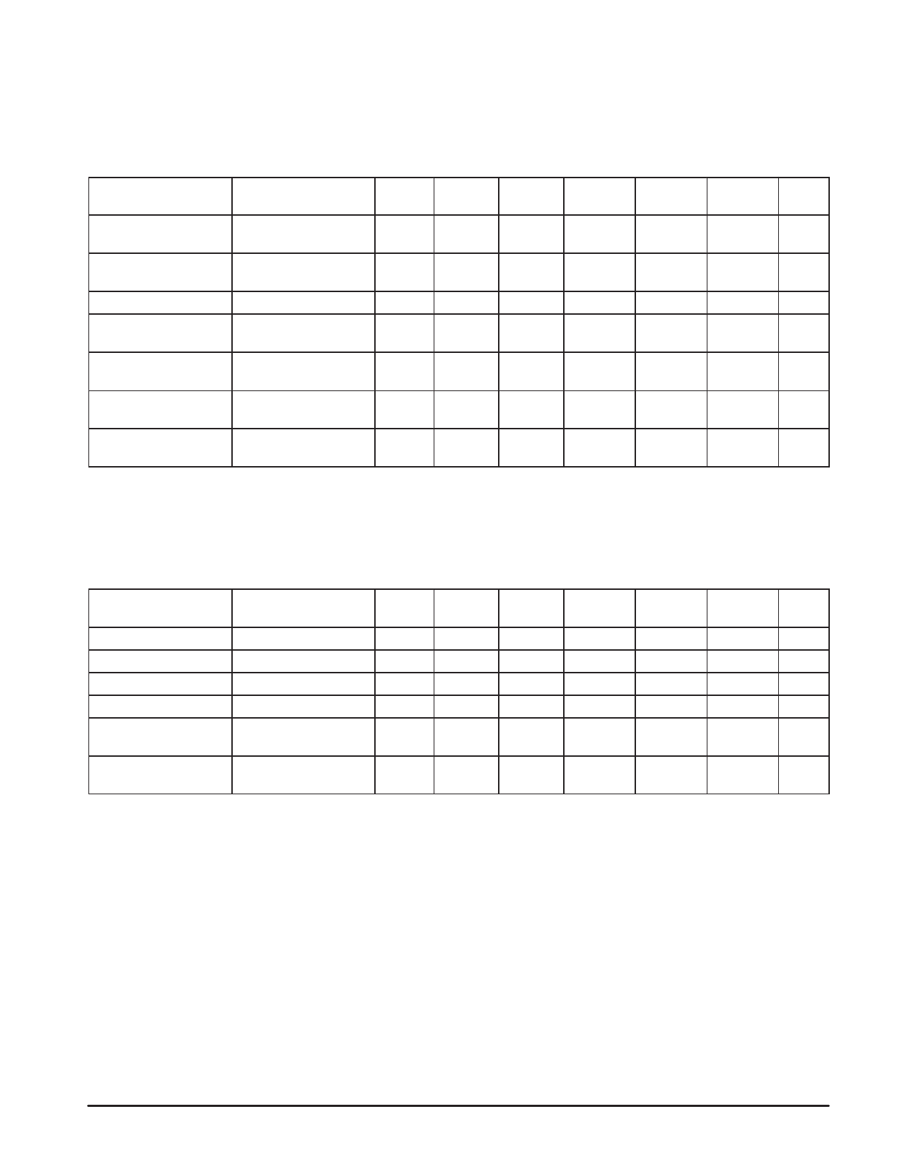
ELECTRICAL CHARACTERISTICS (continued)
RSSI/Carrier Detect
Connect 0.01 µF to Gnd from “RSSI” output pin to form the
carrier detect filter. “CD Out” is an open collector output
which requires an external 100 kΩ pull–up resistor to VCC.
The carrier detect threshold is programmable through the
MPU interface.
(RL = 100 kΩ, VCC = 2.6 V, TA = 25°C.)
Characteristic
Condition
Input Measure
Pin
Pin
Symbol
Min
Typ
Max
Unit
RSSI Output Current
Dynamic Range
–
Mix1 In RSSI
RSSI
–
65
–
dB
Carrier Sense Threshold CD Threshold Adjust = Mix1 In CD Out
VT
–
11
–
mVrms
(10100)
Hysteresis
–
Mix1 In CD Out
Hys
–
Output High Voltage
Vin = 0 µVrms, RL = 100 Mix1 In CD Out
VOH
–
kΩ, CD = (10100)
Output Low Voltage
Vin = 100 µVrms, RL = Mix1 In CD Out
VOL
–
100 kΩ, CD = (10100)
1.5
–
dB
2.6
–
V
0.01
0.4
V
Carrier Sense Threshold Programmable through
–
–
VTrange
– 20
–
Adjustment Range
MPU Interface
11
dB
Carrier Sense Threshold Programmable through
–
–
VTn
–
32
–
–
– Number of Steps
MPU Interface
Data Amp Comparator
Inverting hysteresis comparator. Open collector output
with internal 100 kΩ pull–up resistor. A band pass filter is
connected between the “Det Out” pin and the “DA In” pin with
component values as shown in the attached block diagram.
The “DA In” input signal is ac coupled.
(VCC = 2.6 V, TA = 25°C)
Characteristic
Hysteresis
Threshold Voltage
Input Impedance
Output Impedance
Output High Voltage
Output Low Voltage
Condition
–
–
–
–
Vin = VCC – 1.0 V,
IOH = 0 mA
Vin = VCC – 0.4 V,
IOL = 0 mA
Input Measure
Pin
Pin
Symbol
Min
Typ
Max
Unit
DA In DA Out
Hys
30
40
50
mV
DA In
–
–
DA In
DA Out
DA In
DA Out
DA Out
VT
VCC – 0.9 VCC – 0.7 VCC – 0.5
V
ZI
–
12
–
kΩ
ZO
–
104
–
kΩ
VOH VCC – 0.1
2.6
–
V
DA In DA Out
VOL
–
0.04
0.4
V
6
MOTOROLA RF/IF DEVICE DATA
Share Link: 