MC13143D View Datasheet(PDF) - Motorola => Freescale
Part Name
Description
Manufacturer
MC13143D Datasheet PDF : 9 Pages
| |||
ARCHIVED BY FREESCALE SEMICMOCN1D31U4C3TOR, INC. 2005
APPLICATIONS INFORMATION
Evaluation PC Board
The evaluation PCB is very versatile and is intended to be
used across the entire useful frequency range of this device.
The PC board is laid out to accommodate all SMT
components on the circuit side (see Circuit Side Component
Placement View).
Component Selection
The evaluation PC board is designed to accommodate
specific components, while also being versatile enough to
use components from various manufacturers. The circuit side
placement view is illustrated for the components specified in
the application circuit. The Component Placement View
specifies particular components that were used to achieve
the results shown in the typical curves and tables.
Mixer Input
The mixer input impedance is broadband 50 Ω for
applications up to 2.4 GHz. It easily interfaces with a RF
ceramic filter as shown in the application schematic.
Mixer Linearity Control
The mixer linearity control circuit accepts approximately
0 to 2.3 mA control current. An Input Third Order Intercept
Point, IIP3 of 20 dBm may be achieved at 2.3 mA of control
current (approximately 7.0 mA of additional supply current).
Local Oscillator Inputs
The differential LO inputs are internally biased at
VCC – 1.0 VBE; this is suitable for high voltage and high gain
operation.
For low voltage operation, the inputs are taken to VCC
through 51 Ω.
IF Output
The IF is a differential open collector configuration which is
designed to use over a wide frequency range for up
conversion as well as down conversion.
Input/Output Matching
It is desirable to use a RF ceramic or SAW filter before the
mixer to provide image frequency rejection. The filter is
selected based on cost, size and performance tradeoffs.
Typical RF filters have 3.0 to 5.0 dB insertion loss. The PC
board layout accommodates both ceramic and SAW RF
filters which are offered by various suppliers such as
Siemens, Toko and Murata.
Interface matching between the RF input, RF filter and the
mixer will be required. The interface matching networks
shown in the application circuit are designed for 50 Ω
interfaces.
Differential to single–ended circuit configuration is shown
in the test circuit. 6.0 dB of additional mixer gain can be
achieved by conjugately matching the output of the
MiniCircuits transformer to 50 Ω at the desired IF frequency.
With narrowband IF output matching the mixer performance
is 3.0 dB gain and 12 dB noise figure (see Narrowband 49
and 83 MHz IF Output Matching Options). Typical insertion
loss of the Toko ceramic filter is 3.0 dB. Thus, the overall gain
of the circuit is 0 dB with a 15 dB noise figure.
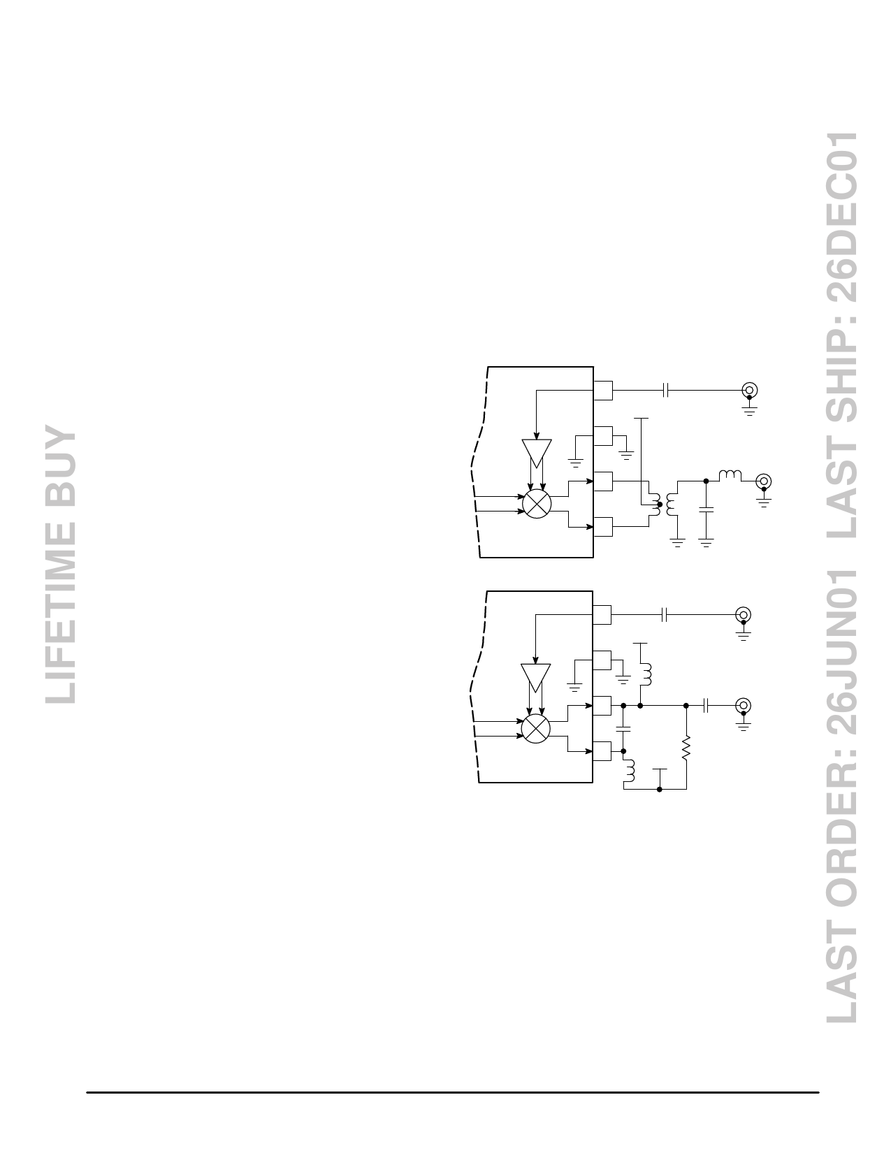
Figure 9. Narrowband IF Output Matching with
16:1 Z Transformer and LC Network
Mixer
IF
Outputs
100 p
8
VCC
7
Mixer
RF Input
Z Transformer
49 MHz
6
16:1
IF
330 nH
Output
36 p
5
Mixer
IF
Outputs
100 p
8
VCC
Mixer
RF Input
7
180 nH
6
10 n
9.2 p
5
9.2 k
180 VCC
nH
83.16 MHz
IF
Output
6
MOTOROLA RF/IF DEVICE DATA
Share Link: 