MC13175D View Datasheet(PDF) - Motorola => Freescale
Part Name
Description
Manufacturer
MC13175D Datasheet PDF : 17 Pages
| |||
MC13175 MC13176
Figure 16 shows the improved hold–in range of the loop.
The ∆fref is moved 950 kHz with over 200 µA swing of control
current for an improved hold–in range of ±15.2 MHz or
± 95.46 Mrad/sec.
Figure 16. MC13176 Reference Oscillator
Frequency versus Oscillator Control Current
10.6
Closed Loop Response:
10.4
fo = 32 x fref
VCC = 3.0 Vdc
ICC = 38 mA
10.2
Pout = 4.8 dB
Imod = 2.0 mA
10
Vref = 500 mVp–p
9.8
9.6
9.4
–150
–100
– 50
0
50
100
I6, OSCILLATOR CONTROL CURRENT (µA)
Lock–in Range/Capture Range
If a signal is applied to the loop not equal to free running
frequency, ff, then the loop will capture or lock–in the
signal by making fs = fo (i.e. if the initial frequency
difference is not too great). The lock–in range can be
expressed as ∆ωL ~ ± 2∂ωn
FM Modulation
Noise external to the loop (phase detector input) is
minimized by narrowing the bandwidth. This noise is minimal
in a PLL system since the reference frequency is usually
derived from a crystal oscillator. FM can be achieved by
applying a modulation current superimposed on the control
current of the CCO. The loop bandwidth must be narrow
enough to prevent the loop from responding to the
modulation frequency components, thus, allowing the CCO
to deviate in frequency. The loop bandwidth is related to the
natural frequency ωn. In the lag–lead design example where
the natural frequency, ωn = 5.0 krad/sec and a damping
factor, ∂ = 0.707, the loop bandwidth = 1.64 kHz.
Characterization data of the closed loop responses for both
the MC13175 and MC13176 at 320 MHz (Figures 7 and 8,
respectively) show satisfactory performance using only a
simple low–pass loop filter network. The loop filter response
is strongly influenced by the high output impedance of the
push–pull current output of the phase detector.
fc = 0.159/RC;
For R = 1.0 k + R7 (R7 = 53 k) and C = 390 pF
fc = 7.55 kHz or ωc = 47 krad/sec
The application example in Figure 18 of a 320 MHz FM
transmitter demonstrates the FM capabilities of the IC. A high
value series resistor (100 k) to Pin 6 sets up the current
source to drive the modulation section of the chip. Its value is
dependent on the peak to peak level of the encoding data
and the maximum desired frequency deviation. The data
input is AC coupled with a large coupling capacitor which is
selected for the modulating frequency. The component
placements on the circuit side and ground side of the PC
board are shown in Figures NO TAG and NO TAG,
respectively. Figure 20 illustrates the input data of a 10 kHz
modulating signal at 1.6 Vp–p. Figures 21 and 22 depict the
deviation and resulting modulation spectrum showing the
carrier null at – 40 dBc. Figure 23 shows the unmodulated
carrier power output at 3.5 dBm for VCC = 3.0 Vdc.
For voice applications using a dynamic or an electret
microphone, an op amp is used to amplify the microphone’s
low level output. The microphone amplifier circuit is shown in
Figure 17. Figure 19 shows an application example for NBFM
audio or direct FSK in which the reference crystal oscillator is
modulated.
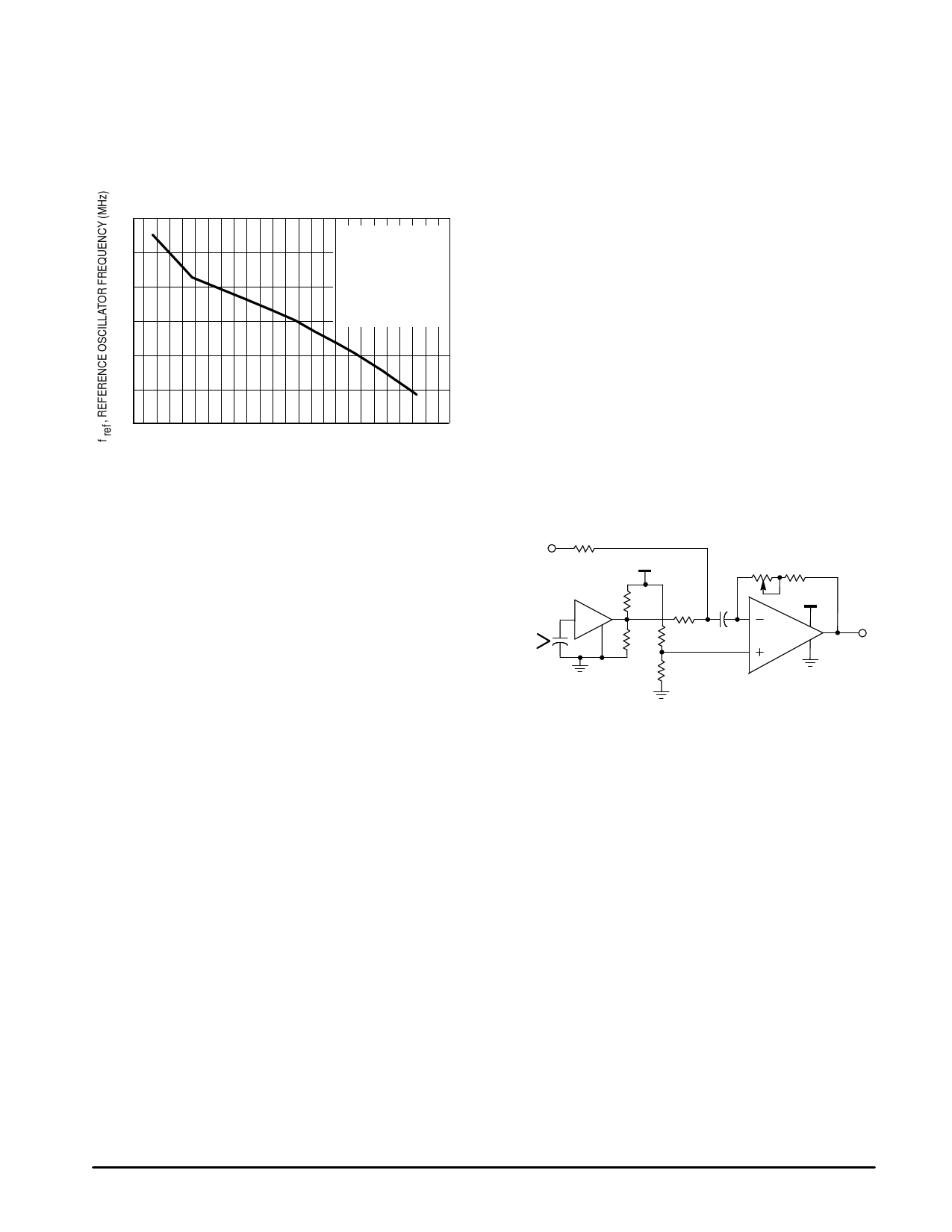
Figure 17. Microphone Amplifier
Data
VCC
Input
100k 120k
3.3k 3.9k 1.0
VCC
Voice
Input
Electret
Microphone
1.0k 10k
10k
MC33171
Data or
Audio
Output
Local Oscillator Application
To reduce internal loop noise, a relatively wide loop
bandwidth is needed so that the loop tracks out or cancels
the noise. This is emphasized to reduce inherent CCO and
divider noise or noise produced by mechanical shock and
environmental vibrations. In a local oscillator application the
CCO and divider noise should be reduced by proper
selection of the natural frequency of the loop. Additional low
pass filtering of the output will likely be necessary to reduce
the crystal sideband spurs to a minimal level.
10
MOTOROLA RF/IF DEVICE DATA
Share Link: 