MC13176 View Datasheet(PDF) - Motorola => Freescale
Part Name
Description
Manufacturer
MC13176 Datasheet PDF : 17 Pages
| |||
MC13175 MC13176
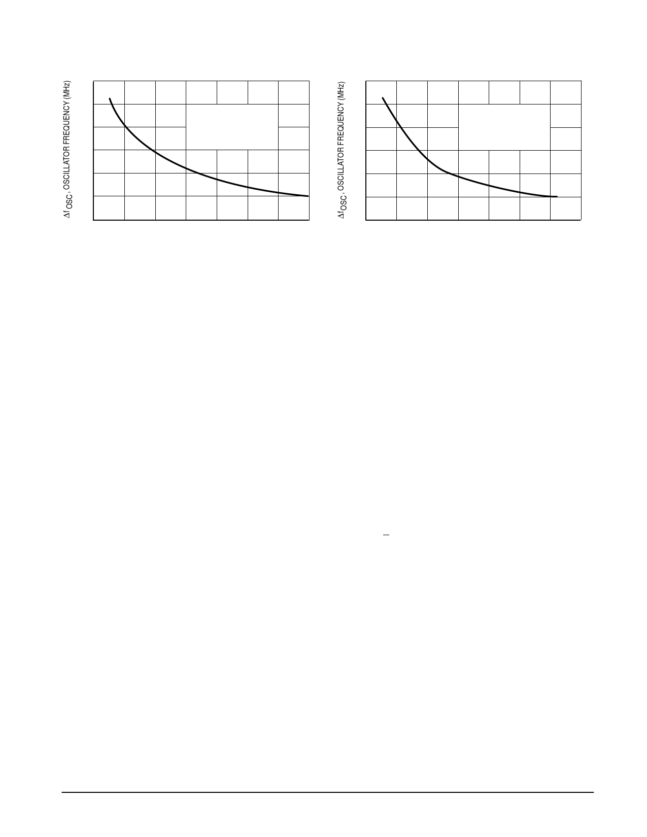
Figure 9. Change in Oscillator Frequency
versus Oscillator Control Current
20
Figure 10. Change in Oscillator Frequency
versus Oscillator Control Current
20
10
10
VCC = 3.0 Vdc
VCC = 3.0 Vdc
0
Imod = 2.0 mA
TA = 25 °C
0
Imod = 2.0 mA
TA = 25 °C
fosc (ICont @ 0) 320 MHz
fosc (ICont @ 0) 450 MHz
–10
–10
– 20
– 20
– 30
– 30
– 40
–100
– 40
0
100 200 300 400 500 600
–100 0
100 200 300 400 500 600
ICont, OSCILLATOR CONTROL CURRENT (µA)
ICont, OSCILLATOR CONTROL CURRENT (µA)
APPLICATIONS INFORMATION
Evaluation PC Board
The evaluation PCB, shown in Figures NO TAG and
NO TAG, is very versatile and is intended to be used across
the entire useful frequency range of this device. The center
section of the board provides an area for attaching all SMT
components to the circuit side and radial leaded components
to the component ground side of the PCB (see Figures
NO TAG and NO TAG). Additionally, the peripheral area
surrounding the RF core provides pads to add supporting
and interface circuitry as a particular application dictates.
This evaluation board will be discussed and referenced in
this section.
Current Controlled Oscillator (Pins 1 to 4)
It is critical to keep the interconnect leads from the CCO
(Pins 1 and 4) to the external inductor symmetrical and equal
in length. With a minimum inductor, the maximum free
running frequency is greater than 1.0 GHz. Since this
inductor will be small, it may be either a microstrip inductor,
an air wound inductor or a tuneable RF coil. An air wound
inductor may be tuned by spreading the windings, whereas
tuneable RF coils are tuned by adjusting the position of an
aluminum core in a threaded coilform. As the aluminum core
coupling to the windings is increased, the inductance is
decreased. The temperature coefficient using an aluminum
core is better than a ferrite core. The UniCoil™ inductors
made by Coilcraft may be obtained with aluminum cores
(Part No. 51–129–169).
Ground (Pins 5, 10 and 15)
Ground Returns: It is best to take the grounds to a
backside ground plane via plated through holes or eyelets at
the pins. The application PCB layout implements this
technique. Note that the grounds are located at or less than
100 mils from the devices pins.
Decoupling: Decoupling each ground pin to VCC isolates
each section of the device by reducing interaction between
sections and by localizing circulating currents.
Loop Characteristics (Pins 6 and 7)
Figure 11 is the component block diagram of the
MC1317XD PLL system where the loop characteristics are
described by the gain constants. Access to individual
components of this PLL system is limited, inasmuch as the
loop is only pinned out at the phase detector output and the
frequency control input for the CCO. However, this allows for
characterization of the gain constants of these loop
components. The gain constants Kp, Ko and Kn are well
defined in the MC13175 and MC13176.
Phase Detector (Pin 7)
With the loop in lock, the difference frequency output of the
phase detector is DC voltage that is a function of the phase
difference. The sinusoidal type detector used in this IC has
the following transfer characteristic:
Ie = A Sin θe
The gain factor of the phase detector, Kp (with the loop in lock)
is specified as the ratio of DC output current, le to phase
error, θe:
Kp = Ie/θe (Amps/radians)
Kp = A Sin θe/θe
Sin θe ~ θe for θe ≤ 0.2 radians;
thus, Kp = A (Amps/radians)
Figures 7 and 8 show that the detector DC current is
approximately 30 µA where the loop loses lock
at θe = + π/2 radians; therefore, Kp is 30 µA/radians.
Current Controlled Oscillator, CCO (Pin 6)
Figures 9 and 10 show the non–linear change in frequency
of the oscillator over an extended range of control current for
320 and 450 MHz applications. Ko ranges from
approximately 6.3x10⁵ rad/sec/µA or 100 kHz/µA (Figure 9)
to 8.8x10⁵ rad/sec/µA or 140 kHz/µA (Figure 10) over a
relatively linear response of control current (0 to 100 µA). The
oscillator gain factor depends on the operating range of the
control current (i.e., the slope is not constant). Included in the
CCO gain factor is the internal amplifier which can sink and
source at least 30 µA of input current from the phase
detector. The internal circuitry at Pin 6 limits the CCO control
current to 50 µA of source capability while its sink capability
exceeds 200 µA as shown in Figures 9 and 10. Further
information to follow shows how to use the full capabilities of
the CCO by addition of an external loop amplifier and filter
(see Figure 15). This additional circuitry yields at Ko =
0.145 MHz/µA or 9.1x10⁵ rad/sec/µA.
MOTOROLA RF/IF DEVICE DATA
7
Share Link: 