MC13175D View Datasheet(PDF) - Motorola => Freescale
Part Name
Description
Manufacturer
MC13175D Datasheet PDF : 17 Pages
| |||
MC13175 MC13176
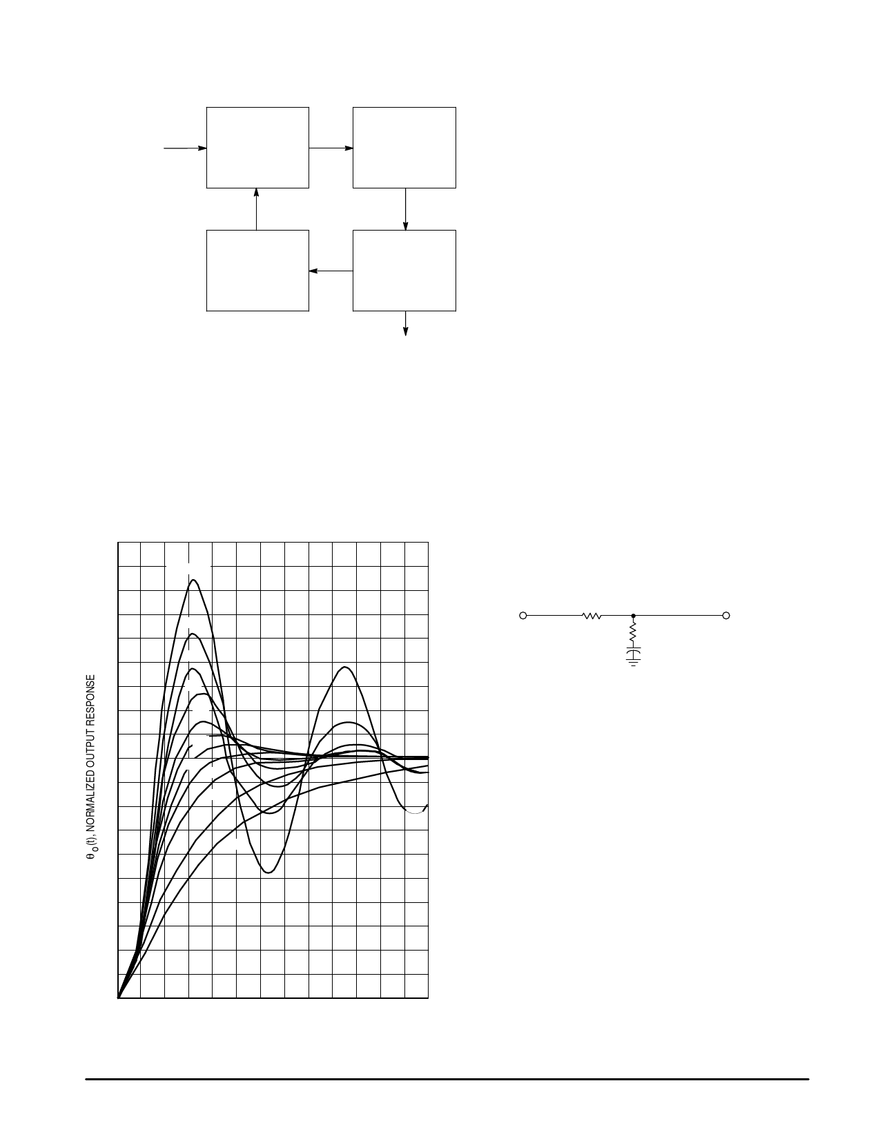
Figure 11. Block Diagram of MC1317XD PLL
θi(s)
fi = f ref
Pins 9,8
Phase
Detector
Kp = 30 µA/rad
θe(s)
Low Pass
Filter
Kf
Pin 7
fn = fo/N
θn(s) = θo(s)/N
Pin 6
Divider
Kn = 1/N
N = 8 : MC13175
N = 32 : MC13176
Amplifier and
θo(s) Current Controlled
Oscillator
Ko = 0.91Mrad/sec/µA
Pins 13,14
fo = nfi
Where: Kp = Phase detector gain constant in
= µA/rad; Kp = 30 µA/rad
Kf = Filter transfer function
Kn = 1/N; N = 8 for the MC13175 and
Ko = 1/N; N = 32 for the MC13176
= CCO gain constant in rad/sec/µA
Ko = 9.1 x 10⁵ rad/sec/µA
Loop Filtering
The fundamental loop characteristics, such as capture
range, loop bandwidth, lock–up time and transient response
are controlled externally by loop filtering.
The natural frequency (ωn) and damping factor (∂) are
important in the transient response to a step input of phase or
frequency. For a given ∂ and lock time, ωn can be determined
from the plot shown in Figure 12.
Figure 12. Type 2 Second Order Response
1.9
1.8
ζ = 0.1
1.7
1.6
0.2
1.5
1.4
0.3
1.3
0.4
1.2
0.5
1.1
0.6
1.0
0.7
0.8
0.9
1.0
0.8
0.7
1.5
2.0
0.6
0.5
0.4
0.3
0.2
0.1
0
0 1.0 2.0 3.0 4.0 5.0 6.0 7.0 8.0 9.0 10 11 12 13
ωnt
For ∂ = 0.707 and lock time = 1.0 ms;
then ωn = 5.0/t = 5.0 krad/sec.
The loop filter may take the form of a simple low pass
filter or a lag–lead filter which creates an additional pole at
origin in the loop transfer function. This additional pole
along with that of the CCO provides two pure integrators
(1/s2). In the lag–lead low pass network shown in Figure
13, the values of the low pass filtering parameters R1, R2
and C determine the loop constants ωn and ∂. The
equations t1 = R1C and t2 = R2C are related in the loop filter
transfer functions F(s) = 1 + t2s/1 + (t1 + t2)s.
Figure 13. Lag–Lead Low Pass Filter
Vin
R1
R2
VO
C
The closed loop transfer function takes the form of a 2nd
order low pass filter given by,
H(s) = KvF(s)/s + KvF(s)
From control theory, if the loop filter characteristic has F(0) =
1, the DC gain of the closed loop, Kv is defined as,
Kv = KpKoKn
and the transfer function has a natural frequency,
ωn = (Kv/t1 + t2)1/2
and a damping factor,
∂ = (ωn/2) (t2 + 1/Kv)
Rewriting the above equations and solving for the MC13176
with ∂ = 0.707 and ωn = 5.0 k rad/sec:
Kv = KpKoKn = (30) (0.91 106) (1/32) = 0.853 106
t1 + t2 = Kv/ωn2 = 0.853 106/(25 106) = 34.1 ms
t2 = 2∂/ωn = (2) (0.707)/(5 103) = 0.283 ms
t1 = (Kv/ωn2) – t2= (34.1 – 0.283) = 33.8 ms
8
MOTOROLA RF/IF DEVICE DATA
Share Link: 