MC13028AD View Datasheet(PDF) - Motorola => Freescale
Part Name
Description
Manufacturer
MC13028AD Datasheet PDF : 20 Pages
| |||
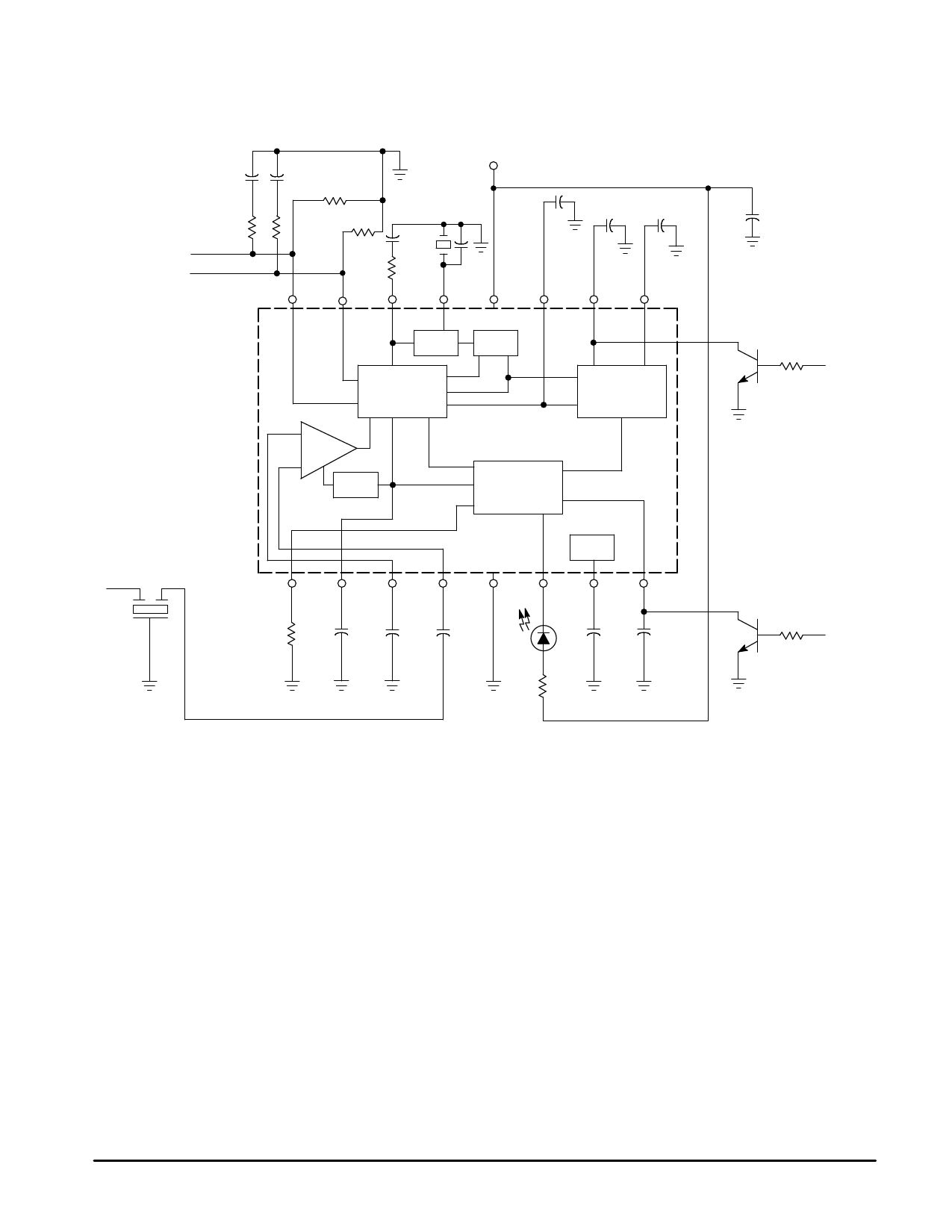
MC13028A
Figure 1. Typical Circuit for E.T.R. Applications
Right Output
Left Output
NRSC Roll–Off Filter
VCC
RO
RO
+
47 µF
(Note 1) 47
16
15
14
(Note 2)
0.22 µF
(Note 4)
43 pF
Pilot
(Note 3)
Input
13
12
11
0.47 µF 10 µF
+
+
Pilot Q
Input
10
Pilot I
Input
9
VCO
B8
AM Stereo
Decoder
Pilot Tone
Detector
IF
Amp
AGC
Signal Quality
Detector
RF AGC’d IF Signal from
Mixer (450 kHz from
Tuner IC Section)
1
2
3
4
5
Stereo
AGC IF
IF
Gnd
Threshold Adjust
Bypass Bypass Input
+
+
R1
10 µF 0.47 µF 0.01 µF
(Note 5)
Reg
6
7
Stereo Ref
Indicator
+
8
Blend
+
10 µF 10 µF (Note 6)
+
47 µF
Optional
Force to
Mono
Scan
Mute
NOTES: 1. The 47 µF capacitor is recommended to be a low leakage type capacitor. Leakage current due to this capacitor causes
increase in stereo distortion and decreased separation performance.
2. The recommended source for this part is Murata Products. CSA3.60MGF108. The location of this part should be carefully
considered during the layout of the decoder circuit. This part should not be near the audio signal paths, the 25 Hz pilot filter
lines, or the VCC high current lines, and the ceramic element ground line should be direct to the chassis ground lead in order
to avoid any oscillator inter–modulation.
3. The 43 pF capacitor is recommended to be a NPO type ceramic part. Changing the value of this capacitor alters the lock
range of the decoder PLL.
4. The tolerance on the value of the 0.22 µF capacitor should be within ± 20% for the full design temperature range of operation.
Any reduction in the value of this capacitor due to temperature excursions will reduce the pilot tone circuit sensitivity.
5. The 0.47 µF capacitor is recommended to be a low ESR type capacitor, (less than 1.5 Ω) in order to avoid increased audio
output distortions under weak input signal conditions with higher modulation levels.
6. The scan/mute function is located on the Blend pin at Pin 8. To provide this function, Pin 8 should be pulled down below 0.3 V
until the decoder and the synthesizer have both locked to a new station.
MOTOROLA ANALOG IC DEVICE DATA
7
Share Link: 