MC1378P View Datasheet(PDF) - Motorola => Freescale
Part Name
Description
Manufacturer
MC1378P
Motorola => Freescale

MC1378P Datasheet PDF : 6 Pages
| |||
MC1378
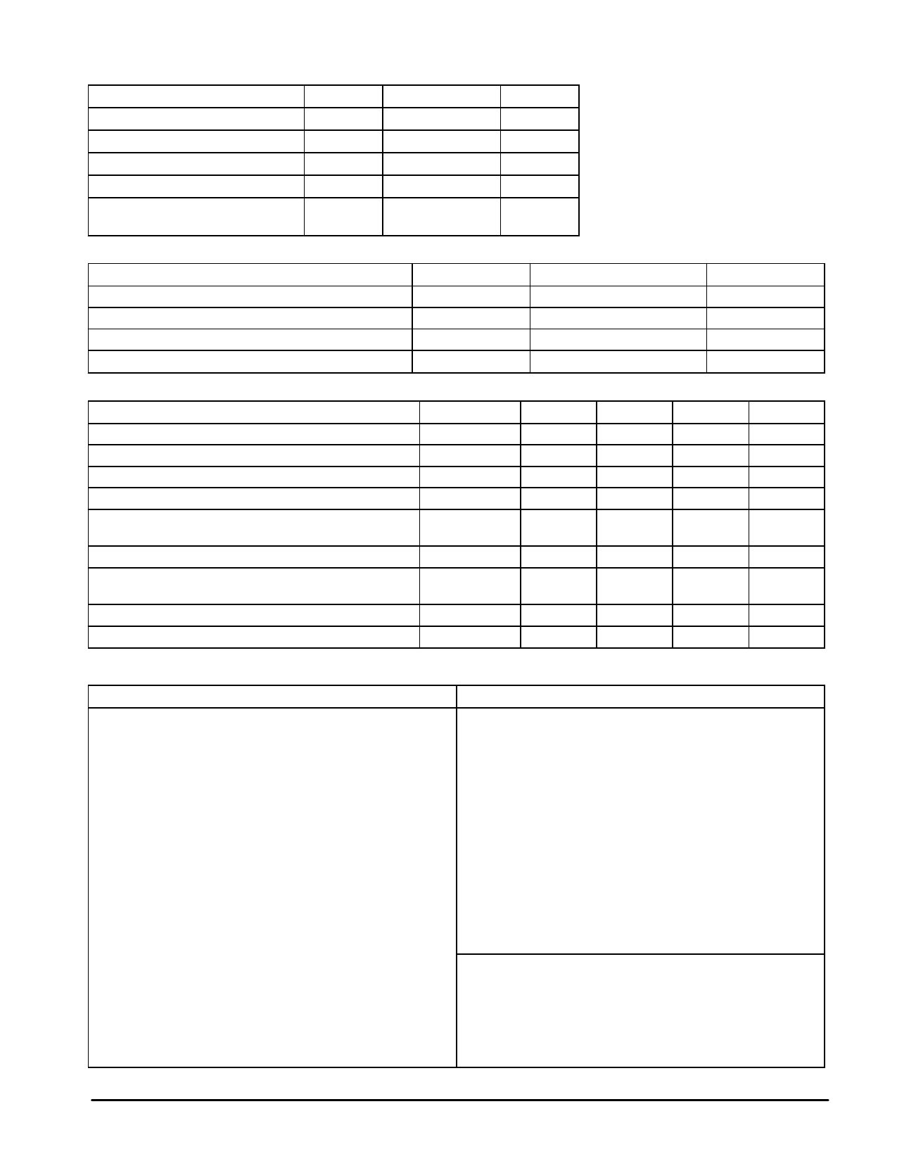
MAXIMUM RATINGS
Rating
Supply Voltage
Operating Temperature
Storage Temperature
Junction Temperature
Power Dissipation, Package
Derate above 25°C
Symbol
VCC
TA
Tstg
TJ(max)
PD
Value
6.0
0 to +70
–65 to +150
150
1.25
10
Unit
Vdc
°C
°C
°C
W
mW/°C
RECOMMENDED OPERATING CONDITIONS
Condition
Supply Voltage
RGB Input for 100% Saturation
Color Oscillator Input Level
Video Input, Positive
Pin
28, 36
14, 15, 16
8
24
ELECTRICAL CHARACTERISTICS (VCC = 5.0 V, TA = 25°C, circuit of Figure 4 or 5)
Characteristics
Pin
Min
Supply Current
28, 36
–
Video Output, Open Circuit, Positive
27
–
Modulation Angle (R – Y) to (B – Y)
–
87
RGB Input Impedance
14, 15, 16
–
Local/Remote Switch (TTL)
High
1
–
Low
Horizontal Sync Input, Negative Going
(TTL)
40
–
Vertical Sync Output, Negative Going,
Remote Mode
38
–
(TTL)
Composite Sync Output, Negative Going
(TTL)
39
–
Burst Gate Output, Positive Going
(TTL)
5
–
Value
5.4 ± 0.25
1.0
0.5
1.0
Typ
100
2.0
90
10
Remote
Local
4.3
4.3
4.3
4.3
Unit
Vdc
Vpp
Vpp
Vpp
Max
Unit
–
mAdc
9.4
Vpp
93
Degrees
–
kΩ
–
–
–
Vpp
–
Vpp
–
Vpp
–
Vpp
Description of Operation – Refer to Figures 3, 4
Remote Mode
Local Mode
The incoming remote video signal (Pin 24) supplies all
synchronizing information. A discussion of the function of the
phase detectors helps to clarify the lockup method:
The MC1378 and a video system combine to provide a fully
synchronized standard signal source. In this case, composite sync
must be supplied by the video system or other time base system.
In the MC1378 the phase detectors operate as follows:
PD1 locks the internally counted–down 4 MHz horizontal VCO
to the incoming horizontal sync. It is fast acting, to follow
VCR source fluctuations.
PD1 locks the internally counted–down 4 MHz horizontal VCO
to a Horizontal Sync signal (at Pin 40) from the video
system (counted down from 36 MHz)
PD2 locks the 36 MHz clock VCO, which is divided down by
the video system, to the divided down horizontal VCO.
PD2 not used in LOCAL MODE.
PD3 not used in LOCAL MODE.
PD3 is a gated phase detector which locks the 14 MHz crystal
oscillator, divided by 4, to the incoming color burst.
PD4 active, but providing an arbitrary phase shift setting
between the color oscillator and the output burst phase.
PD4 controls an internal phase shifter to assure that the
outgoing color burst is the same phase as incoming burst
at PD3.
PD5 not used in REMOTE MODE
PD5 locks the 36 MHz clock VCO (which is divided down by
the video system) to the 14 MHz (crystal) color oscillator.
The 14 MHz is, therefore, the system standard in LOCAL
MODE, and is not DC controlled.
Vertical lock is obtained by continuously resetting the sync
generator in the video system with separated vertical sync from the
MC1378, Pin 38. This signal is TTL level vertical block sync,
negative going. The horizontal sync from the video system to Pin 40
is also TTL level with sync negative going. The local/remote switch,
Pin 1, is in local mode when grounded, remote mode when taken
to 5.0 V. The overlay control, Pin 25, has an analog characteristic,
centered about 1.0 V, which allows fading from local to remote.
COMPOSITE VIDEO GENERATION
The color encoding at the RGB signals is done exactly as in
the MC1377. Composite chroma is looped out at Pins 18 and 20
to allow the designer to choose band shaping. Luminance is
similarly brought out (Pins 17 and 22) to permit installation of
the appropriate delay.
Composite sync output, Pin 39, and burst gate output, Pin 5,
are provided for convenience only.
2
MOTOROLA ANALOG IC DEVICE DATA
Share Link: