MIC841 View Datasheet(PDF) - Micrel
Part Name
Description
Manufacturer
MIC841 Datasheet PDF : 8 Pages
| |||
Micrel, Inc.
Application Information
Output
The MIC841N and MIC842N outputs are an open-drain
MOSFET, so most applications will require a pull-up
resistor. The value of the resistor should not be too large
or leakage effects may dominate. 470kΩ is the
maximum recommended value. Note that the output of
“N” version may be pulled up as high as 6V regardless of
the ICs supply voltage. The “H” and “L” versions of the
MIC841 and MIC842 have a push-pull output stage, with
a diode clamped to VDD. Thus, the maximum output
voltage of the “H” and “L” versions is VDD. See “Electrical
Characteristics.”
When working with large resistors on the input to the
devices, a small amount of leakage current can cause
voltage offsets that degrade system accuracy. The
maximum recommended total resistance from VIN to
ground is 3MΩ. The accuracy of the resistors can be
chosen based upon the accuracy required by the
system. The inputs may be subjected to voltages as high
as 6V steady-state without adverse effects of any kind
regardless of the ICs supply voltage. This applies even if
the supply voltage is zero. This permits the situation in
which the IC’s supply is turned off, but voltage is still
present on the inputs. See “Electrical Characteristics.”
Programming the MIC841 Thresholds
The low-voltage threshold is calculated using:
VIN(LO )
−
VREF
⎜⎛
⎝
R1 + R2 + R3
R2 + R3
⎟⎞
⎠
The high-voltage threshold is calculated using:
VIN(HI)
−
VREF
⎜⎛
⎝
R1
+
R2 +
R3
R3 ⎟⎞
⎠
where, for both equations:
In order to provide the additional criteria needed to solve
for the resistor values, the resistors can be selected
such that they have a given total value, that is, R1 + R2
+ R3 = RTOTAL. A value such as 1MΩ for RTOTAL is a
reasonable value because it draws minimum current but
has no significant effect on accuracy.
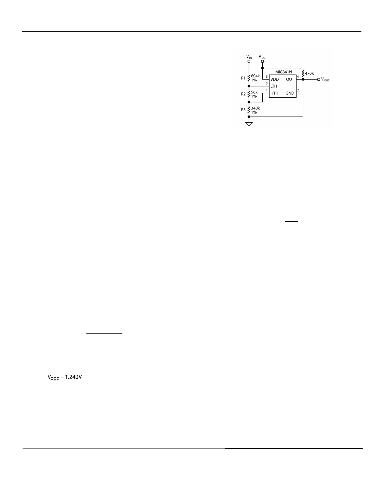
MIC841/2
Figure 1. MIC841 Example Circuit
Once the desired trip points are determined, set the
VIN(HI) threshold first.
For example, use a total of 1MΩ = R1 + R2 + R3. For a
typical single-cell lithium ion battery, 3.6V is a good “high
threshold” because at 3.6V the battery is moderately
charged. Solving for R3:
VIN(HI)
−
3.6V
− 1.24⎜⎛ 1MΩ
⎝ R3
⎟⎞
⎠
R3 = 344kΩ
Once R3 is determined, the equation for VIN(LO) can be
used to determine R2. A single lithium-ion cell, for
example, should not be discharged below 2.5V. Many
applications limit the drain to 3.1V. Using 3.1V for the
VIN(LO) threshold allows calculation of the two remaining
resistor values.
VIN(LO)
−
3.1V
− 1.24⎜⎛ 1MΩ
⎝ R2 + 344k
⎟⎞
⎠
R2 = 56kΩ
1MΩ - (R2 - R3) = R1
R1 = 600kΩ
The accuracy of the resistors can be chosen based upon
the accuracy required by the system.
March 2011
6
M9999-030811-B
Share Link: 