ML6652 View Datasheet(PDF) - Micro Linear Corporation
Part Name
Description
Manufacturer
ML6652
Micro Linear Corporation

ML6652 Datasheet PDF : 28 Pages
| |||
PIN DESCRIPTIONS (continued)
Pin No. Signal Name
I/O
Description
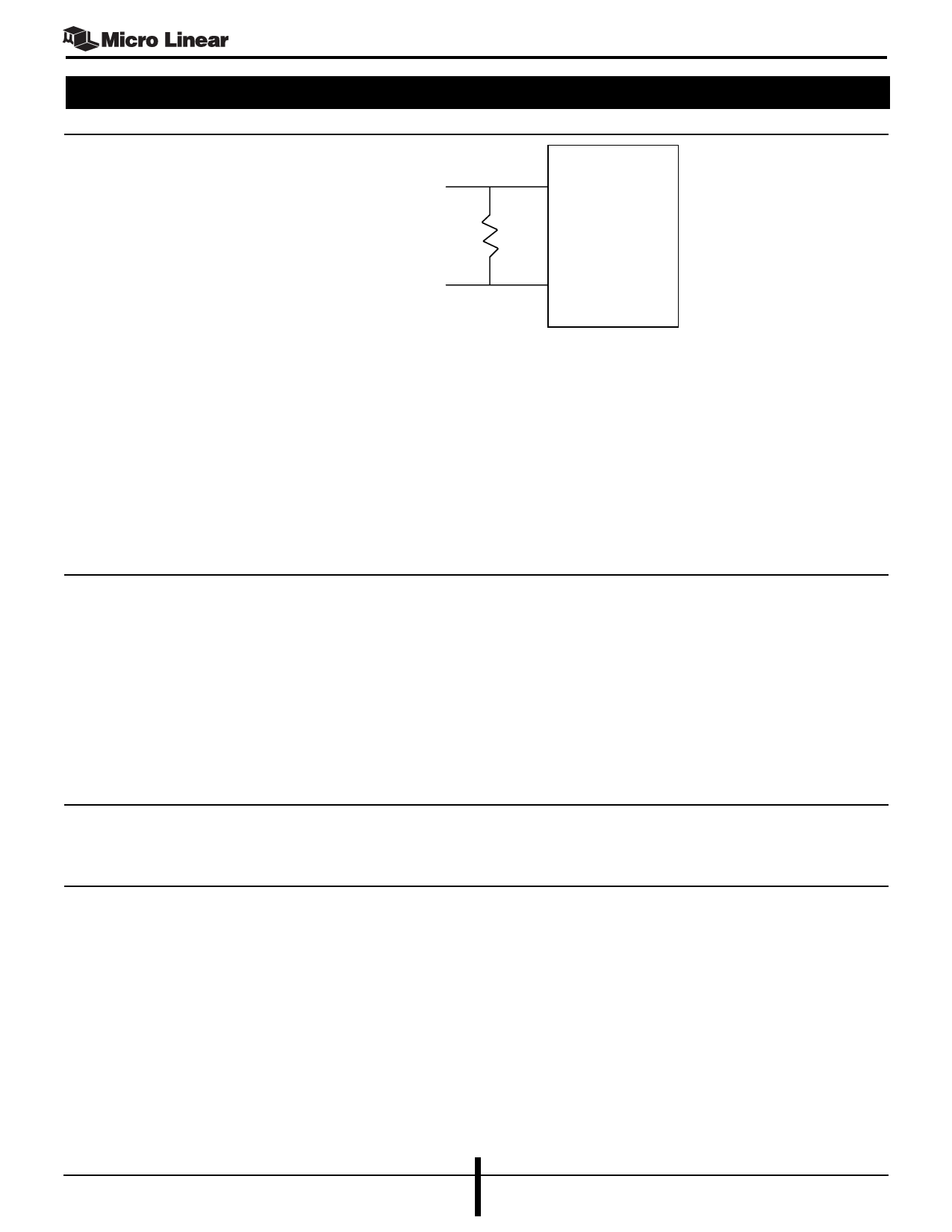
Input from
transformer
circuit Pulse
H1019 or
equiv.
100Ω
ML6652
10
11
Figure 1. Twisted Pair Interface Mode Input Networks
ML6652
37
REQSD
39
SDTH
21
IOUT
22
IOUT#
PECL/LVPECL Compatible Interface Mode:
PECL/LVPECL compatible interface positive and complementary inputs. These
inputs form a differential input pair that receives 100BASE-FX, 100BASE-SX,
FLNP Bursts, or 10BASE-FL signal from a fiber optic PMD. The PMD outputs
should be AC coupled to these inputs with .1µF capacitors. The common mode
voltage is set internally with ~1kΩ or so resistors from each input pin to an on-
chip voltage reference. The positive output of the PMD (high during the high-
light state) must connect to TPINP and the complementary output of the PMD
must connect to TPINN
I
The two operating modes available for this pin are selected with the
configuration pin PECLTP or the configuration bit PECLTP <30.3>
Twisted Pair Interface Mode:
Equalizer bias resistor pin. An external resistor connected between this pin and
ground sets internal currents that control the receiver’s adaptive equalizer
transfer function. The recommended resistor value is 5kΩ, 1%
PECL/LVPECL Compatible Interface Mode:
This input pin is connected to the Signal Detect (SD) output of a fiber optic
PMD module. The voltage level at this pin is compared to the voltage level at
pin SDTH to determine the logic value. If it is lower, then the input at TPINP/
TPINN is rejected. If it is higher, then the input at TPINP/TPINN is passed to the
internal circuits
I
The voltage at this pin is a single ended PECL/LVPECL reference. Refer to
description of SDFO and REQSD pins. This pin is not used if the TPINP/TPINN
interface and the FOINP/FOINN are not setup for PECL/LVPECL compatible
mode. In such a case, the SDTH pin should be set to VCC
O
The two operating modes available for these pins are selected with the
configuration pin PECLQU or the configuration bit PECLQU <30.7>
O
Fiber Optic Interface Mode:
IOUT (pin 21) becomes the output connection to the cathode of an external
fiber optic LED. The output data is NRZI encoded 100BASE-FX or 100BASE-
SX symbols during 100Mbps mode, Manchester encoded 10BASE-FL data or
OPT_IDL (10BASE-FL idle signal) during 10Mbps mode, and FLNP Bursts
during Auto-Negotiation.
IOUT# (pin 22) is optionally used to provide current peaking. If peaking is
9
January 2004
Final Datasheet
DS6652-F-02
Share Link: