MSM6641 View Datasheet(PDF) - Oki Electric Industry
Part Name
Description
Manufacturer
MSM6641 Datasheet PDF : 6 Pages
| |||
MSM6641/6641E-xx
¡ Semiconductor
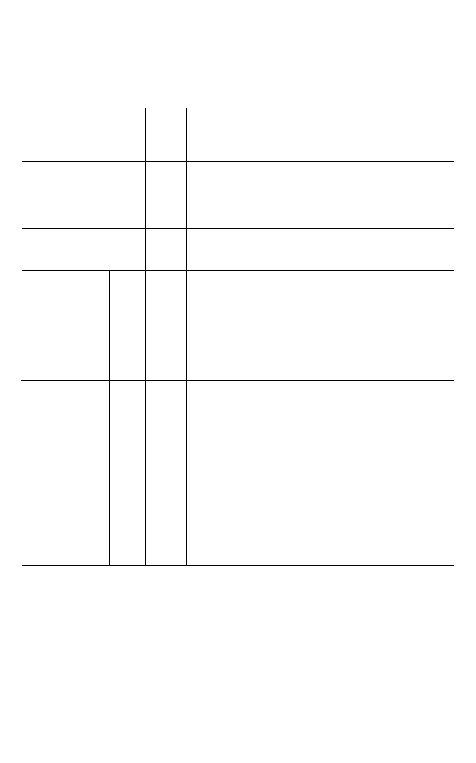
PIN DESCRIPTIONS
Pin
Symbol
Type
Description
8
VDD
– Power supply pin (1.5 V/3.0 V)
11
VSS
– Ground pin
9
XT
I Oscillation input pin: a ceramic oscillator is connected.
10
XTB
O Oscillation output pin: a ceramic oscillator is connected.
Remote control output pin: This pin outputs the remote control
7
RCOUT
O
output set by the program. A "L" level is output at the time of reset.
12
RESET
System reset input pin: when a "L" level is applied to this pin, the
I
microcontroller's internal state is initialized and the program starts from
ROM address 000H.
6
P0.0
4-bit input port: normally used as the input of key matrix. A pull-down
5
4
PORT 0
P0.1
P0.2
I
resistor or high impedance can be selected for each bit by the input
pull-down control register (PCHZO) of PORT0.
3
P0.3
2
P1.0
1
P1.1
24
PORT 1 P1.2
23
P1.3
4-bit input port: normally used as the input of key matrix. A pull-down
resistor or high impedance for PORT1 can be selected by bit 0 of input
I
pull-down control register (PCHZX) of PORTS1 and 2.
22
PORT 2 P2.0
1-bit input port: normally used as the input of key matrix. A pull-down
I resistor or high impedance for P2.0 can be selected by bit 1 of input
pull-down control register (PCHZX) of PORTS1 and 2.
21
P3.0
20
19
PORT 3
P3.1
P3.2
18
P3.3
4-bit output port: normally used as the key return signal source of key
O
matrix.
17
P4.0
16
15
P4.1
PORT 4 P4.2
14
P4.3
4-bit output port: normally used as the key return signal source of key
O
matrix.
13
PORT 5 P5.0
1-bit output port: normally used as the key return signal source of key
O
matrix.
228
Share Link: 