MSM7557 View Datasheet(PDF) - Oki Electric Industry
Part Name
Description
Manufacturer
MSM7557 Datasheet PDF : 25 Pages
| |||
¡ Semiconductor
MSM7557
(Continued)
Name
FDE
BIT
Function
Frame synchronous signal detector control.
When digital "0" is applied to this pin, FD pin is fixed to "0" level. RT and RD always work.
When digital "1" is applied to this pin, frame synchronous detector works, and RT and RD pins are fixed
to "1" level untill synchronous signal detector detects frame synchronous signal and FD becomes "1" level.
Refer to Fig.3 (receive signal timing).
Bit synchronous signal detector control.
When BIT and FDE pins are digital "1" level and when bit synchronous signal and frame synchronous
signal are detected continously, FD becomes digital "1".
When BIT pin is digital "0" level and FDE pin is digital "1" level and when 16-bit frame synchronous
signal is detected, FD pin becomes digital "1" level.
Refer to FPS pin detection.
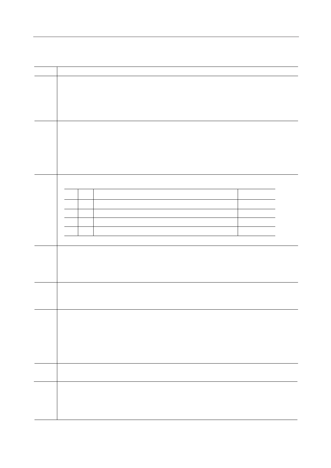
Frame synchronous pattern control.
BIT FPS
Detect pattern
Receiver
00
FPS
01
1 0 0 1 0 0 1 1 0 0 1 1 0 1 1 0 (=9336H) Handset side
1 1 0 0 0 1 0 0 1 1 0 1 0 1 1 0 (=C4D6H) Base station
1 0 1 0 1 0 1 0 0 1 0 0 1 1 0 0 1 1 0 1 1 0 (=A9336H) Handset side
1 1 1 0 1 0 1 1 0 0 0 1 0 0 1 1 0 1 0 1 1 0 (=AC4D6H) Base station
(Note : This pattern is for Japanese Cordless Telephone.)
Frame synchronous detector output.
When receive data correspond to detection pattern, FD pin is held to digital "1" level.
FD
When FDE is applied to digital "0" level, FD pin is reset to digital "0" level.
And at the full power down state (PDN = "1", RVE = "0" ), FD pin is reset to digital "0" level.
Demodulator serial data output.
RD The data are synchronized with the re-generated timing clock of RT.
When FDE is digital "1" level and also FD is digital "0" level, RD is fixed to digital "1" level.
Receive data timing clock output.
This signal is re-generated by internal digital PLL. The falling edge of this clock output is coincident
with the transitions of RD.
RT
The rising edge of RT can be used to latch the valid receive data.
When FDE pin is applied to digital "1" level and also FD pin output digital "0" level, RT pin is fixed to
digital "1" level. Refer to Fig.3.
Receive voice signal control.
RVE
Refer to RVO pin description.
Power supply.
VDD
This device is sensitive to power supply noises as switched capacitor tequniques are utilized.
A bypass capacitor of more than 10 mF between VDD and GND pin should be connected to ensure
the performance.
8/25
Share Link: 