MCM69T618 View Datasheet(PDF) - Motorola => Freescale
Part Name
Description
Manufacturer
MCM69T618 Datasheet PDF : 10 Pages
| |||
AC OPERATING CONDITIONS AND CHARACTERISTICS
(VCC = 3.3 V + 10%, – 5%, TJ = 20 to 110°C, Unless Otherwise Noted)
Input Timing Measurement Reference Level . . . . . . . . . . . . . . . 1.5 V
Input Pulse Levels . . . . . . . . . . . . . . . . . . . . . . . . . . . . . . . . . 0 to 3.0 V
Input Rise/Fall Time . . . . . . . . . . . . . . . . . . . . . . . . . . . . . . . . . . . . 3 ns
Output Timing Reference Level . . . . . . . . . . . . . . . . . . . . . . . . . . 1.5 V
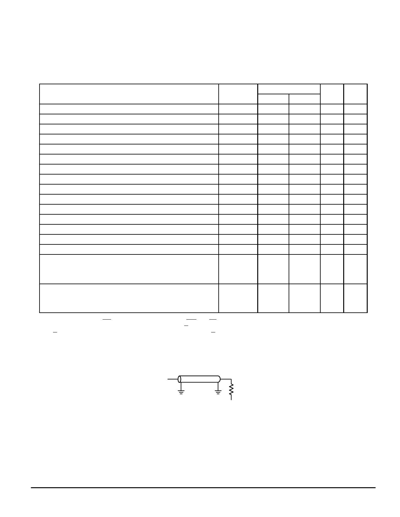
Output Load . . . . . . . . . . . . . . See Figure 1 Unless Otherwise Noted
READ/WRITE CYCLE TIMING (See Notes 1, 2, and 3)
MCM69T618–5
Parameter
Symbol
Min
Max
Unit
Cycle Time
tKHKH
10
—
ns
Clock High Pulse Width
tKHKL
3.5
—
ns
Clock Low Pulse Width
tKLKH
3.5
—
ns
Clock High to Match Valid
tKHMV
—
5
ns
Clock Access Time
tKHQV
—
5
ns
Output Enable to Output Valid
tGLQV
—
5
ns
Match Output Enable to Match Valid
tMGLMV
—
5
ns
Clock High to Output Active
tKHQX1
0
—
ns
Clock High to Output Change
tKHQX2
1.5
—
ns
Clock High to Match Output Change
tKHMX
1.5
—
ns
Output Enable to Output Active
tGLQX
0
—
ns
Match Output Enable to Match Active
tMGLMX
0
—
ns
Output Disable to Q High–Z
tGHQZ
—
5
ns
Match Output Disable to Match High–Z
tMGHMZ
—
5
ns
Clock High to Q High–Z
tKHQZ
1.5
5
ns
Setup Times:
Address
tAVKH
2.5
Data In
tDVKH
Write
tWVKH
Enable
tEVKH
—
ns
Hold Times:
Address
tKHAX
0.5
Data In
tKHDX
Write
tKHWX
Enable
tKHEX
—
ns
NOTES:
1. “Write” applies to the SW signal. “Enable” applies to SE0, SE1, and DE signals.
2. All read and write cycle timings are referenced from K or G.
3. G is a don’t care after write cycle begins. To prevent bus contention, G should be negated prior to start of write cycle.
4. Tested per AC Test Load (See Figure 1).
5. This parameter is sampled and not 100% tested.
6. Measured at ± 200 mV from steady state.
Notes
4
4
4
4, 5
4
4, 5
4, 5
5, 6
5
5, 6
OUTPUT
Z0 = 50 Ω
RL = 50 Ω
VT = 1.5 V
Figure 1. AC Test Loads
MOTOROLA FAST SRAM
MCM69T618
7
Share Link: 