NJU6434C View Datasheet(PDF) - Japan Radio Corporation
Part Name
Description
Manufacturer
NJU6434C Datasheet PDF : 14 Pages
| |||
NJU6434
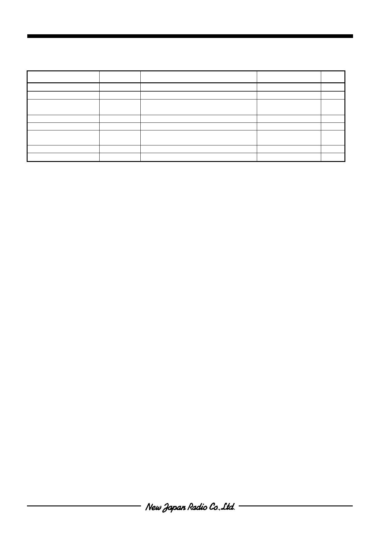
! ABSOLUTE MAXIMUM RATINGS
PARAMETER
SYMBOL
CONDITIONS
RATINGS
Ta=25°C
UNIT
Operating Voltage (1)
VDDmax VDD Terminal, Ta=25°C
-0.3~+7.0
V
Operating Voltage (2)
Input Voltage (1)
VLCDmax
VI
VLCD Terminal, Ta=25°C
CE, SCL, DATA, MODE,
INHb Terminals, Ta=25°C
-0.3~+7.0
V
-0.3~+7.0
V
Input Voltage (2)
VI
OSC1, OSC2 Terminals
-0.3~VDD+0.3
V
Output Voltage
VO
OSC1, OSC2 Terminals
-0.3~VDD+0.3
V
Power Dissipation
Pdmax
Glass epoxy board (4-layer)
76.2mm x 114.3mm x 1.6mm
1600(QFN64-S4)
1900(QFP64-H2)
mW
Operating Temperature
Topr
-
-40~+85
°C
Storage Temperature
Tstg
-
-55~+125
°C
Note 1) All voltage values are specified as VSS = 0V.
Note 2) If the LSI is used on condition above the absolute maximum ratings, the LSI may be destroyed. Using
the LSI within electrical characteristics is strongly recommended for normal operation. Use beyond the
electric characteristics conditions will cause malfunction and poor reliability.
Note 3) Turn on VDD first then turn on VLCD must be required.
Note 4) Decoupling capacitor should be connected between VDD and VSS , VLCD and VSS due to the stabilized
operation for the LSI.
Ver.2009-11-12
-9-
Share Link: 