NTE1851 View Datasheet(PDF) - NTE Electronics
Part Name
Description
Manufacturer
NTE1851 Datasheet PDF : 4 Pages
| |||
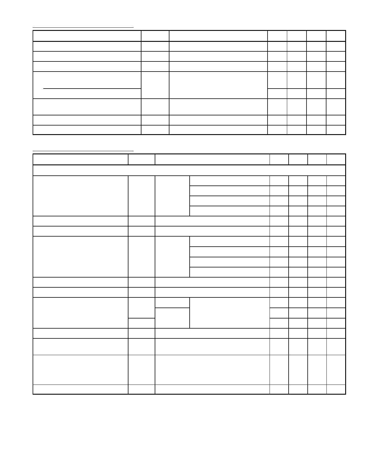
DC Electrical Characteristics:
Parameter
Supply Voltage Range (Pin10)
Repetitive Peak Output Current
Total Quiescent Current
Switching Level 11
OFF
ON
Impedance Between Pin10 & Pin6;
Pin10 & Pin8
Standby Current
Switch–On Current (Pin11)
Symbol
VCC
IORM
ITOT
V11
Test Conditions
|ZOFF| Standby Position V11 < 1.8V
ISB V11 = 0 to 0.8V
ISO V11 ≤ V10
Min Typ Max Unit
6 – 18 V
––4A
– 75 75 mA
V
– – 1.8
3.0 – – V
100 – – kΩ
–
1 100 µA
– 10 100 µA
AC Electrical Characteristics: (TA = +25°C, VCC = 14.4V, f = 1kHz unless otherwise specified)
Parameter
Symbol
Test Conditions
Min Typ Max Unit
Bridge–Tied Load Application (BTL)
Output Power with Bootstrap
Open–Loop Voltage Gain
Closed–Loop Voltage Gain
Output Power without Bootstrap
PO RL = 4Ω VCC = 14.4V, dTOT = 0.5% 15.5 18.0 – W
VCC = 14.4V, dTOT = 10% 20 24 – W
VCC = 13.2V, dTOT = 0.5% – 15 – W
VCC = 13.2V, dTOT = 10% – 20 – W
GO
– 75 – dB
GC Note 2
– 40 – dB
PO Note 3
VCC = 14.4V, dTOT = 0.5% – 12 12 W
VCC = 14.4V, dTOT = 10% – 15 15 W
Frequency Response at –3dB
B Note 4
VCC = 13.2V, dTOT = 0.5% –
9
9W
VCC = 13.2V, dTOT = 10% – 12 12 W
20 – 20 Hz
Input Impedance
Noise Input Voltage (RMS Value)
|Zi|
VN(RMS)
Note 5
RS = 0Ω
RS = 10kΩ
f = 20Hz to 20kHz
1 – – MΩ
– 0.2 0.2 mV
– 0.35 0.35 mV
VN
Supply Voltage Ripple Rejection RR f = 100Hz
– 0.25 0.8 mV
42 50 50 dB
DC Output Offset Voltage
Between the Outputs
|∆V5–9|
– 2 50 mV
Loudspeaker Protection
(All Conditions)
Maximum DC Voltage
(Across the Load)
|∆V5–9|
––1V
Power Bandwidth
B –1dB, dTOT = 0.5%
30 – 40 kHz
Note 1. The internal circuit impedance at Pin11 is > 5kΩ if V11 > V10.
Note 2. Closed–Loop voltage gain can be chosen between 32 and 56dB (BTL), and is determined
by external components.
Note 3. Without the bootstrap the 100µF capacitor between Pin5 and Pin6 (Pin8 and Pin9) can be
omitted. Pin6, Pin8, and Pin10 have to be interconnected.
Note 4. Frequency response externally fixed.
Note 5. The input impedance in the test circuit is typically 100kΩ.
Share Link: 