NTE1851 View Datasheet(PDF) - NTE Electronics
Part Name
Description
Manufacturer
NTE1851 Datasheet PDF : 4 Pages
| |||
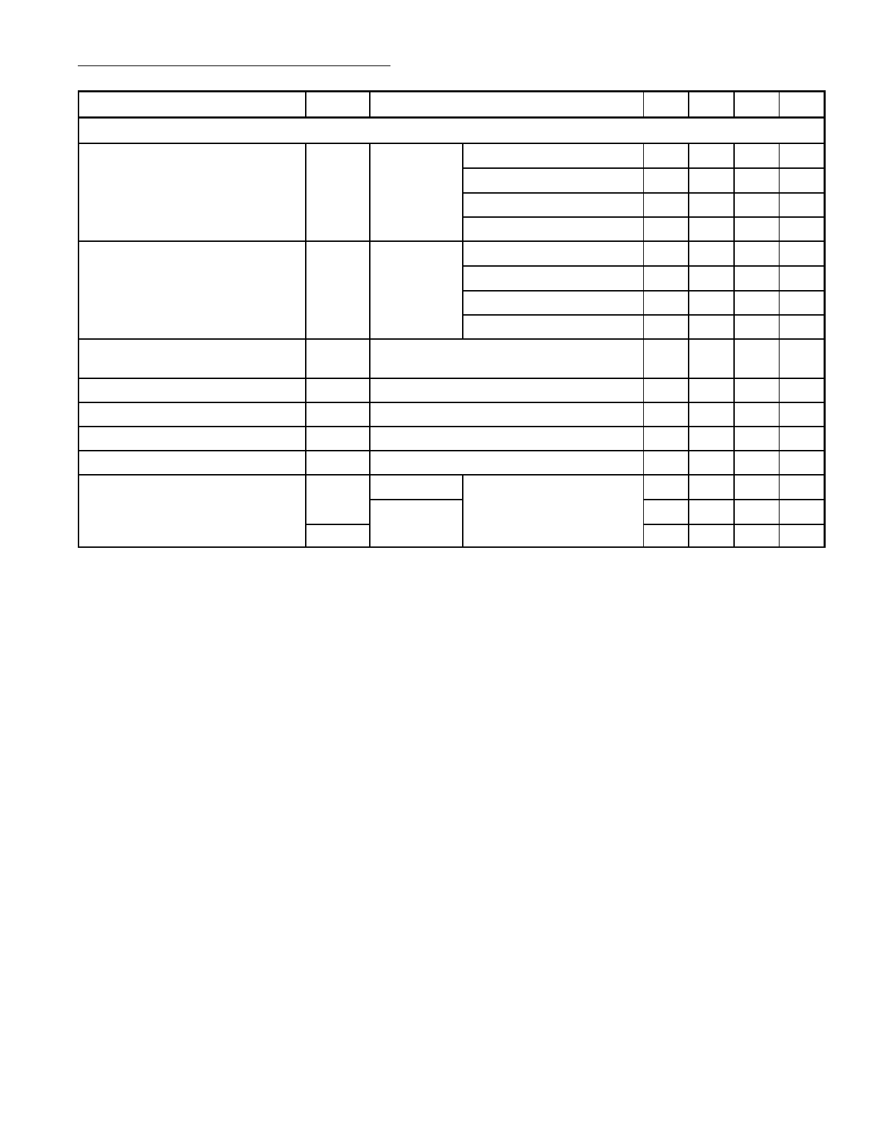
AC Electrical Characteristics (Cont’d): (TA = +25°C, VCC = 14.4V, f = 1kHz unless otherwise
specified)
Parameter
Symbol
Test Conditions
Min Typ Max Unit
Stereo Application
Output Power with Bootstrap
PO dTOT = 10% VCC = 14.4V, RL = 4Ω
Note 6
VCC = 14.4V, RL = 2Ω
VCC = 13.2V, RL = 4Ω
VCC = 13.2V, RL = 4Ω
Output Power with Bootstrap
PO dTOT = 0.5% VCC = 14.4V, RL = 4Ω
Note 6
VCC = 14.4V, RL = 2Ω
VCC = 13.2V, RL = 4Ω
VCC = 13.2V, RL = 4Ω
Output Power without Bootstrap PO dTOT = 10%, VCC = 14.4V, RL = 4Ω,
Note 3, Note 6, & Note 7
6 7 –W
10 12 – W
– 6 –W
– 10 – W
– 5.5 – W
– 9.0 – W
– 4.5 – W
– 7.5 – W
– 6 –W
Frequency Response at –3dB
B Note 4
40 – 20 kHz
Supply Voltage Ripple Rejection RR Note 8
– 50 – dB
Channel Separation
Closed–Loop Voltage Gain
Noise Input Voltage (RMS Value)
α RS = 10kΩ, f = 1kHz
GC Note 9
VN(RMS) RS = 0Ω
f = 20Hz to 20kHz
RS = 10kΩ
VN
40 50 – dB
– 40 – dB
– 0.15 – mV
– 0.25 – mV
– 0.2 – mV
Note 1. The internal circuit impedance at Pin11 is > 5kΩ if V11 > V10.
Note 2. Closed–Loop voltage gain can be chosen between 32 and 56dB (BTL), and is determined
by external components.
Note 3. Without the bootstrap the 100µF capacitor between Pin5 and Pin6 (Pin8 and Pin9) can be
omitted. Pin6, Pin8, and Pin10 have to be interconnected.
Note 4. Frequency response externally fixed.
Note 5. The input impedance in the test circuit is typically 100kΩ.
Note 6. Output power is measured directly at the output pins of the IC.
Note 7. A resistor of 56kΩ between Pin3 and Pin7 to reach symmetrical clipping.
Note 8. Supply voltage ripple rejection measured with a source impedance of 0Ω (Maximum ripple
amplitude: 2V).
Note 9. Closed–Loop voltage gain can be chosen between 26 and 50dB (Stereo), and is determined
by external components.
Share Link: 