P89C51X2 View Datasheet(PDF) - Philips Electronics
Part Name
Description
Manufacturer
P89C51X2 Datasheet PDF : 48 Pages
| |||
Philips Semiconductors
80C51 8-bit Flash microcontroller family
4K/8K/16K/32K Flash
Preliminary data
P89C51X2/52X2/54X2/58X2
DESCRIPTION
The Philips microcontrollers described in this data sheet are
high-performance static 80C51 designs. They are manufactured in
an advanced CMOS process and contain a non-volatile Flash
program memory. They support both 12-clock and 6-clock operation.
The P89C51X2 and P89C52X2/54X2/58X2 contain 128 byte RAM
and 256 byte RAM respectively, 32 I/O lines, three 16-bit
counter/timers, a six-source, four-priority level nested interrupt
structure, a serial I/O port for either multi-processor
communications, I/O expansion or full duplex UART, and on-chip
oscillator and clock circuits.
In addition, the devices are static designs which offer a wide range
of operating frequencies down to zero. Two software selectable
modes of power reduction — idle mode and power-down mode —
are available. The idle mode freezes the CPU while allowing the
RAM, timers, serial port, and interrupt system to continue
functioning. The power-down mode saves the RAM contents but
freezes the oscillator, causing all other chip functions to be
inoperative. Since the design is static, the clock can be stopped
without loss of user data. Then the execution can be resumed from
the point the clock was stopped.
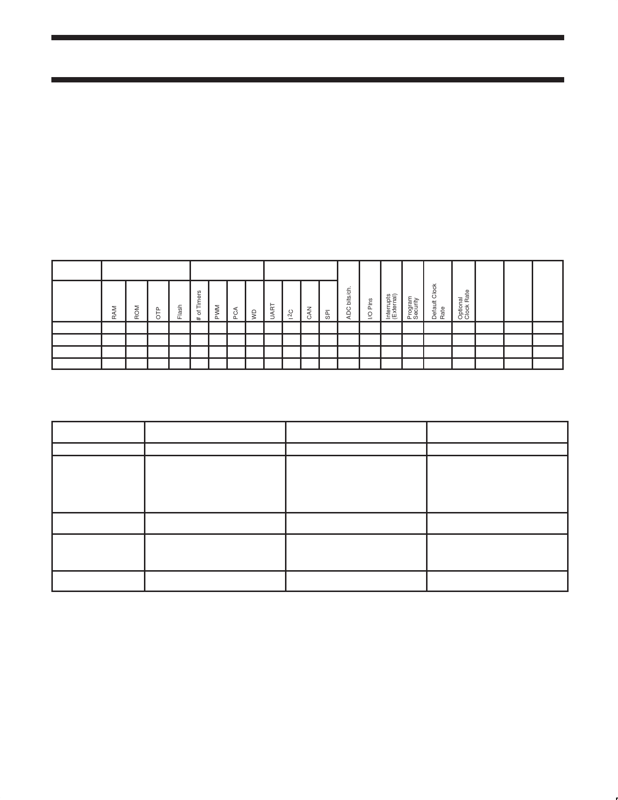
SELECTION TABLE
For applications requiring more Flash and RAM, as well as more
on-chip peripherals, see the P89C66x and P89C51Rx2 data sheets.
Type
Memory
Timers
Serial Interfaces
P89C58X2 256B –
P89C54X2 256B –
P89C52X2 256B –
P89C51X2 128B –
– 32K 3 – – – n – – –
– 16K 3 – – – n – – –
–
8K 3
–
– –n–
–
–
–
4K 3
–
– –n–
–
–
Max.
Freq.
at 6-clk
/ 12-clk
(MHz)
Freq.
Range
at 3V
(MHz)
Freq.
Range
at 5V
(MHz)
–
32 6 (2) n 12–clk 6-clk 20/33
–
0–20/33
–
32 6 (2) n 12–clk 6-clk 20/33
–
0–20/33
–
32 6 (2) n 12–clk 6-clk 20/33
–
0–20/33
–
32 6 (2) n 12–clk 6-clk 20/33
–
0–20/33
NOTE:
1. I2C = Inter-Integrated Circuit Bus; CAN = Controller Area Network; SPI = Serial Peripheral Interface; PCA = Programmable Counter Array;
ADC = Analog-to-Digital Converter; PWM = Pulse Width Modulation
DEVICE COMPARISON TABLE
Item
Type Description
PROGRAMMING
ALGORITHM
Quad Flat Package
type
Package identifiers
Flash Memory program
and erase cycles
P89C5xX2 devices (this data
sheet)
P89C5xX2Bxx/P89C5xX2Fxx
When using a parallel programmer,
be sure to select P89C5xX2 devices.
IF DEVICES ARE NOT YET
SELECTABLE ASK YOUR
PROGRAMMER VENDOR FOR A
SOFTWARE UPDATE
LQFP package (P89C5xX2xBD)
PLCC = A
LQFP = BD
PDIP = N
10,000 program and erase cycles
P89C5xBx devices (separate data
sheet)
P89C5xBx
When using a parallel programmer,
be sure to select P89C5xBx devices.
IF DEVICES ARE NOT YET
SELECTABLE ASK YOUR
PROGRAMMER VENDOR FOR A
SOFTWARE UPDATE
LQFP package (P89C5xBBD)
PLCC = A
LQFP = BD
PDIP = P
10,000 program and erase cycles
P89C5xUxx devices
(discontinued)
P89C5xUBxx/P89C5xUFxx
When using a parallel programmer,
be sure to select P89C5xUxxx
devices.
PQFP package (P89C5xUxBB)
PLCC = AA
LQFP = BB
PDIP = PN
100 program and erase cycles
2002 Jun 06
2
Share Link: 