PC911P View Datasheet(PDF) - Sharp Electronics
Part Name
Description
Manufacturer
PC911P Datasheet PDF : 5 Pages
| |||
s Recommended Operating Conditions
Parameter
Low level input current
High level input current
High level enable voltage
Low level enable voltage
Supply voltage
Fanout ( TTL load )
Operating temperature
Symbol
MIN.
MAX.
Unit
I FL
0
250
µA
I FH
7
15
mA
V EH
2.0
V CC
V
V EL
0
0.8
V
V CC
4.5
5.5
V
N
-
8
-
T opr
0
70
˚C
1. When the enable input is not used, please connect to VCC.
2. In order to stabilize power supply line, connect a by-pass ceramic
capacitor ( 0.01 to 0.1 µ F ) between VCC and GND at the position within
1cm from pin.
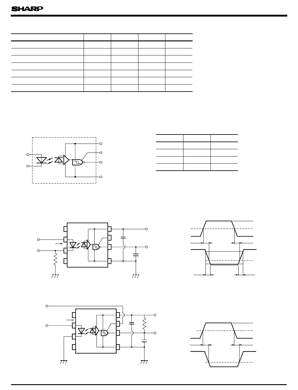
Block Diagram
Anode
Cathode
VCC
VE (Enable)
VO
GND
Truth table
Input
H
L
H
L
Enable
H
H
L
L
L : Logic ( 0)
H : Logic ( 1)
Z : High impedance
Output
L
H
Z
Z
PC911
Fig. 1 Test Circuit for t PHL, t PLH, t r and t f
Pulse input
IF
47 Ω
CL includes the probe
and wiring capacitance.
Fig. 2 Test Circuit for t EHL and tELH
Pulse input V E
IF = 7.5mA
5V
0.1 µ F
VO
CL
5V
0.1
µ F R L= 350 Ω
VO
CL
CL includes the probe
and wiring capacitance.
IF
tPHL
VO
tf
VE
tEHL
VO
7.5mA
3.75mA
0mA
tPLH
90% 5V
10 %
tr
1.5V
VOL
3V
1.5V
0V
tELH
5V
1.5V
VOL
Share Link: 