ST7FSCR14M1 View Datasheet(PDF) - STMicroelectronics
Part Name
Description
Manufacturer
ST7FSCR14M1
STMicroelectronics

ST7FSCR14M1 Datasheet PDF : 102 Pages
| |||
ST7SCR
4 FLASH PROGRAM MEMORY
4.1 Introduction
The ST7 dual voltage High Density Flash (HD-
Flash) is a non-volatile memory that can be electri-
cally erased as a single block or by individual sec-
tors and programmed on a Byte-by-Byte basis us-
ing an external VPP supply.
The HDFlash devices can be programmed and
erased off-board (plugged in a programming tool)
or on-board using ICP (In-Circuit Programming) or
IAP (In-Application Programming).
The array matrix organisation allows each sector
to be erased and reprogrammed without affecting
other sectors.
4.2 Main Features
s Three Flash programming modes:
– Insertion in a programming tool. In this mode,
all sectors including option bytes can be pro-
grammed or erased.
– ICP (In-Circuit Programming). In this mode, all
sectors including option bytes can be pro-
grammed or erased without removing the de-
vice from the application board.
– IAP (In-Application Programming) In this
mode, all sectors except Sector 0, can be pro-
grammed or erased without removing the de-
vice from the application board and while the
application is running.
s ICT (In-Circuit Testing) for downloading and
executing user application test patterns in RAM
s Read-out protection against piracy
s Register Access Security System (RASS) to
prevent accidental programming or erasing
4.3 Structure
The Flash memory is organised in sectors and can
be used for both code and data storage.
Depending on the overall FLASH memory size in
the microcontroller device, there are up to three
user sectors (see Table 3). Each of these sectors
can be erased independently to avoid unneces-
sary erasing of the whole Flash memory when only
a partial erasing is required.
The first two sectors have a fixed size of 4 Kbytes
(see Figure 6). They are mapped in the upper part
of the ST7 addressing space so the reset and in-
terrupt vectors are located in Sector 0 (F000h-
FFFFh).
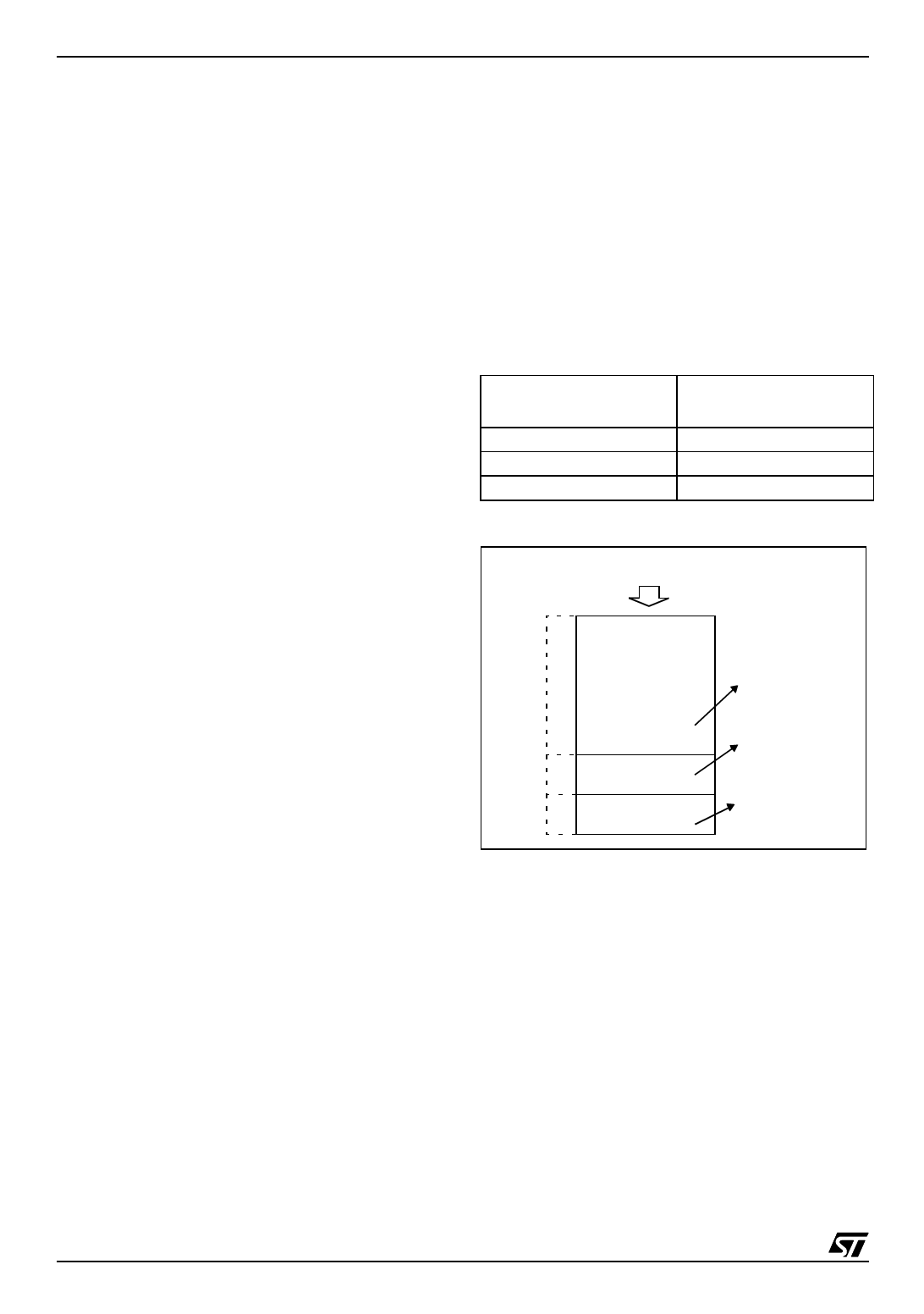
Table 3. Sectors available in FLASH devices
Flash Memory Size
(bytes)
4K
8K
> 8K
Available Sectors
Sector 0
Sectors 0,1
Sectors 0,1, 2
Figure 6. Memory map and sector address
16K USER FLASH MEMORY SIZE
C000h
DFFFh
E000h
EFFFh
F000h
FFFFh
8 Kbytes
SECTOR 2
4 Kbytes
SECTOR 1
4 Kbytes
SECTOR 0
ex.: user program
ex.: user data
+ library
ex.: user system library
+ IAP BootLoader
14/102
1
Share Link: