PDTC115TM View Datasheet(PDF) - Philips Electronics
Part Name
Description
Manufacturer
PDTC115TM Datasheet PDF : 10 Pages
| |||
Philips Semiconductors
PDTC115T series
NPN resistor-equipped transistors; R1 = 100 kΩ, R2 = open
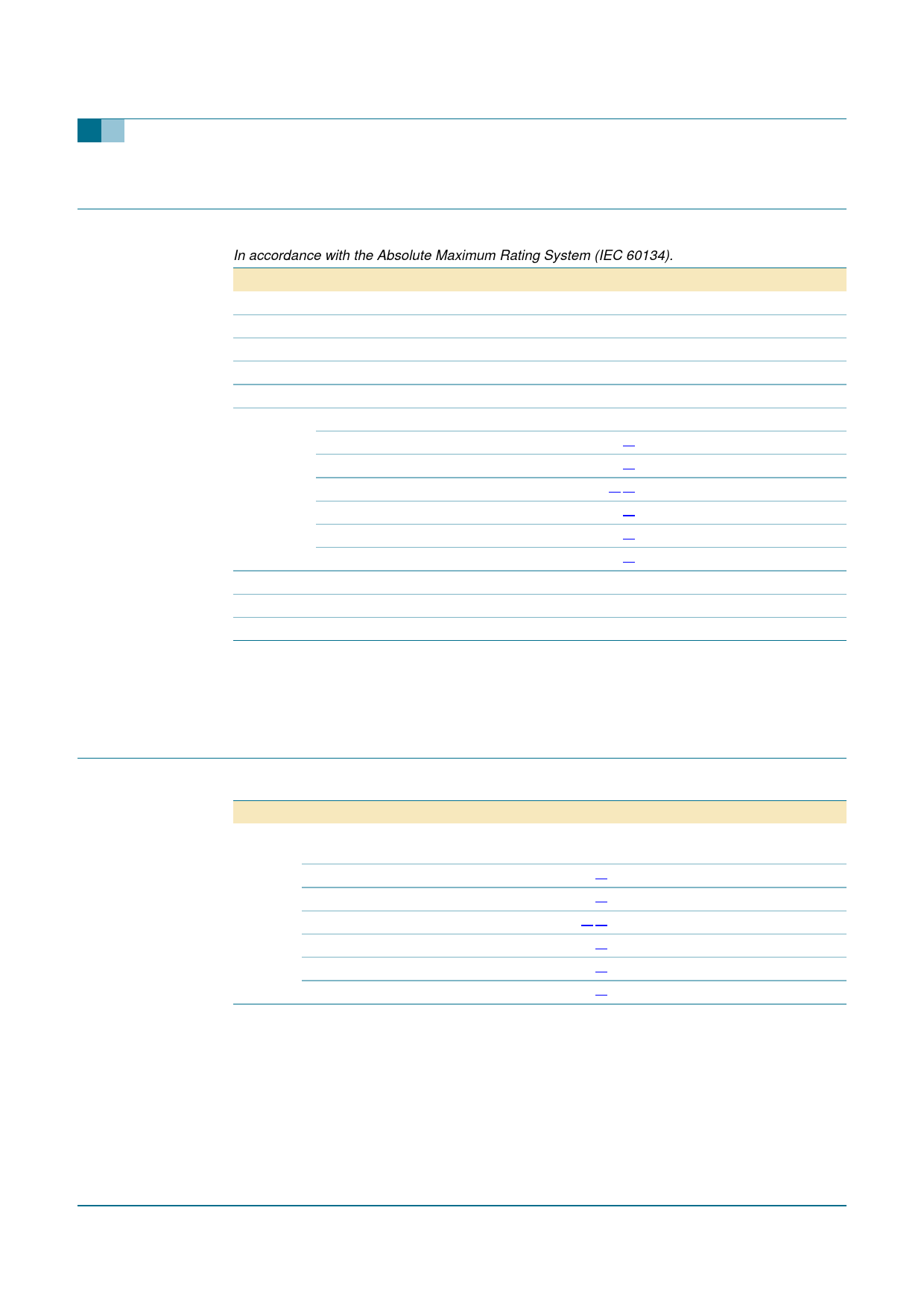
5. Limiting values
Table 6: Limiting values
In accordance with the Absolute Maximum Rating System (IEC 60134).
Symbol Parameter
Conditions
Min
Max
Unit
VCBO
VCEO
VEBO
IO
ICM
Ptot
Tstg
Tj
Tamb
collector-base voltage
collector-emitter voltage
emitter-base voltage
output current (DC)
peak collector current
total power dissipation
SOT416
SOT346
SOT883
SOT54
SOT23
SOT323
storage temperature
junction temperature
ambient temperature
open emitter
-
open base
-
open collector
-
-
-
Tamb ≤ 25 °C
Tamb ≤ 25 °C
Tamb ≤ 25 °C
Tamb ≤ 25 °C
Tamb ≤ 25 °C
Tamb ≤ 25 °C
[1] -
[1] -
[2] [3] -
[1] -
[1] -
[1] -
−65
-
−65
50
V
50
V
5
V
100
mA
100
mA
150
mW
250
mW
250
mW
500
mW
250
mW
200
mW
+150
°C
150
°C
+150
°C
[1] Refer to standard mounting conditions.
[2] Reflow soldering is the only recommended soldering method.
[3] Refer to SOT883 standard mounting conditions; FR4 printed-circuit board with 60 µm copper strip line.
6. Thermal characteristics
Table 7: Thermal characteristics
Symbol Parameter
Conditions
Min
Typ
Max Unit
Rth(j-a)
thermal resistance from in free air
junction to ambient
SOT416
[1] -
-
833
K/W
SOT346
[1] -
-
500
K/W
SOT883
[2] [3] -
-
500
K/W
SOT54
[1] -
-
250
K/W
SOT23
[1] -
-
500
K/W
SOT323
[1] -
-
625
K/W
[1] Refer to standard mounting conditions.
[2] Reflow soldering is the only recommended soldering method.
[3] Refer to SOT883 standard mounting conditions; FR4 printed-circuit board with 60 µm copper strip line.
9397 750 14021
Product data sheet
Rev. 04 — 17 February 2005
© Koninklijke Philips Electronics N.V. 2005. All rights reserved.
4 of 10
Share Link: 